Unlock instant, AI-driven research and patent intelligence for your innovation.

System and method for modulation and demodulation using code subset conversion

A technology of input codes and codes, which is applied in the field of converting input codes into output codes, and can solve problems such as consumption, large space, and high channel bit rate.

Inactive Publication Date: 2010-05-12
MEDIATEK INC
View PDF0 Cites 0 Cited by
  • Summary
  • Abstract
  • Description
  • Claims
  • Application Information

AI Technical Summary

Problems solved by technology

It can be seen that using a complete modulation and demodulation table will not easily achieve a higher channel bit rate, and it will take a considerable amount of space

Method used


Image

  • System and method for modulation and demodulation using code subset conversion
  • System and method for modulation and demodulation using code subset conversion
  • System and method for modulation and demodulation using code subset conversion

Examples


Embodiment

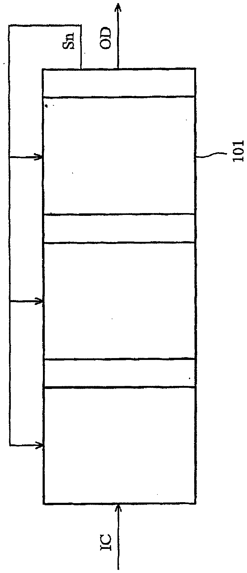
[0034] Figure 4 is a schematic diagram showing a preferred embodiment according to the present invention. like Figure 4 As shown, the input code IC includes multiple input code subsets, and the input code subset 1S 1 ~1S n are transformed into multiple output code subsets 10 1 -10 n . Next, the output code subsets are combined to generate the output code OC corresponding to the input code IC.

[0035] Figure 5A is to show the modulation or demodulation method according to the preferred embodiment of the present invention. exist Figure 5A , step 501 determines a plurality of input code subsets of the input code. Next, step 503 is to convert the input code subsets into multiple output code subsets respectively. Step 505 combines the subsets of output codes to generate output codes to complete the modulation or demodulation of the input codes.

[0036] Figure 5B is displayed Figure 5A Another example of , with Figure 5A compared to, Figure 5B A step 507 is ...


PUM


Abstract

Disclosed is a method for converting an input code into an output code. The method includes: determining a plurality of input code subsets of the input code; converting the input code subsets into a plurality of output code subsets, respectively; and merging the output code subsets to generate the output code.

Description

technical field [0001] The present invention relates to a conversion method, in particular to a method for converting an input code into an output code. Background technique [0002] Eight-to-twelve modulation (ETM) technology is used in a high density digital versatile disc (HD-DVD). That is, an 8-bit symbol (ie, a byte or a data word) is converted into a 12-bit code word stored on the disk. [0003] figure 1 is a schematic diagram showing conventional modulating and demodulating methods. like figure 1 As shown, an input code IC (eg, a data word) is converted into an output code OD (eg, a code word) according to table 101 . Coefficient S called state (state) or condition (case) n It is determined according to the input code IC, output code OD and table 101. For HD-DVD modulation, the input code IC represents an 8-bit data word, the output code OD represents a 12-bit code word, and Table 101 represents the modulation table; however, for HD-DVD demodulation, The input ...

Claims


Application Information

Patent Timeline
Patent Type & Authority Patents(China)
IPC IPC(8): G11B20/10H03M7/30
CPCG11B2220/2579G11B2020/1469G11B20/1426H03M5/145
Inventor 谢嘉鸿刘碧海
Owner MEDIATEK INC