Check patentability & draft patents in minutes with Patsnap Eureka AI!

Injection device

A technology of injection device and injection hole, which is applied in the field of plastic molding devices, can solve the problems of cost, shutdown replacement, cover damage, etc.

Inactive Publication Date: 2007-03-21
意大利S.I.P.A.公司
View PDF0 Cites 0 Cited by
  • Summary
  • Abstract
  • Description
  • Claims
  • Application Information

AI Technical Summary

Problems solved by technology

[0012] Some disadvantages of this solution include damage to the hood due to high operating temperatures, for example, the relatively high cost of the hood itself and the need for regular shutdowns for replacement

Method used


Image

  • Injection device
  • Injection device
  • Injection device

Examples


Embodiment Construction

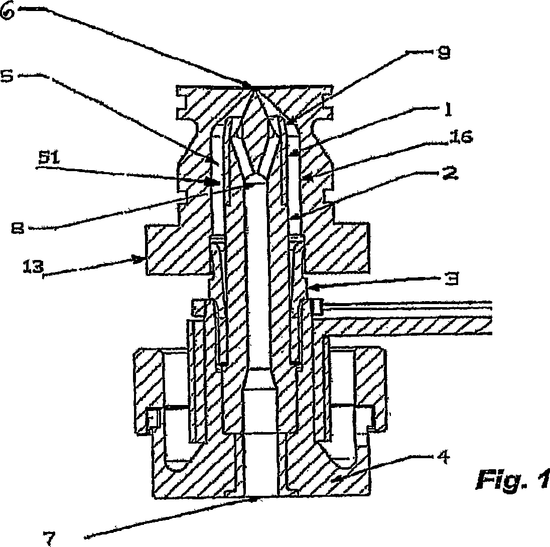
[0027] Fig. 1, Fig. 1A and Fig. 2 have described the first embodiment of a kind of injection device of the present invention, and in described embodiment, injection device comprises tip holder 4 and the heater that is fixed on it by centering ring nut 3 tip. The heating tip comprises a housing 2 in which a passage 8 is connected to the hot half of the plastic material molding mold through a suitable conduit. Reference numeral 7 indicates the end of the channel 8 on the side of the hot half.

[0028] Reference numeral 13 denotes a hollow mold closest to the molding cavity (not shown) of the mold.

[0029] The plastic material that flows out of the hot half of the mold during injection via the inner channel 8 flows out of the housing 2 through the outflow hole 14, is guided by the conical wall on the groove 16 of the mould, reaches the injection hole 6, and then reaches the injection hole 6 according to the design. The molding cavity where the molded object is finally shaped. ...


PUM


Abstract

A nozzle comprises a hollow element comprising a recess and an injection hole ( 6 ) to inject fluid plastic into a mould, a heating tip which penetrates inside the recess and forms, together with the recess itself, a holding cavity ( 5 ) into which the channels ( 14 ) run. The holding cavity ( 5 ) comprises narrow section ( 52 ) which separates the holding cavity ( 5 ) into a rear portion ( 51 ) and a front portion ( 50 ), in order to reduce or completely prevent exchanges of fluid plastic between the two areas.

Description

technical field [0001] The present invention relates to an apparatus for the molding of injectable materials, especially plastics, when molding from one injectable material in order to mold different materials, for example between two different production batches Avoid or at any rate reduce contamination of the moldings during job changeovers. Background technique [0002] In the so-called "hot runner technique" for plastic molding, molten plastic from a plastification screw is conveyed into a heated cavity - the "hot half" ( hot half)-in which a series of channel branches transport the plastic to the individual cavities of the mold, or mold cavities. [0003] Molten plastic is thus injected into the respective mold cavity via an injection terminal containing the heating tip secured to the tip holder by a centering ring nut. [0004] When the mold is in the injection position, the pin generally extends into a generally cylindrical insulated cavity formed by the die punch. ...

Claims


Application Information

Patent Timeline
Patent Type & Authority Applications(China)
IPC IPC(8): B29C45/27
CPCB29C45/27B29C2045/2769
Inventor 马迪欧·佐帕斯丹尼斯·吉亚科马奇卢卡·芬达斯科卡罗·科洛齐
Owner 意大利S.I.P.A.公司
Features
  • R&D
  • Intellectual Property
  • Life Sciences
  • Materials
  • Tech Scout
  • Unparalleled Data Quality
  • Higher Quality Content
  • 60% Fewer Hallucinations
Learn More