Method for control video frequency coding rate

A bit rate control and video coding technology, applied in the field of video coding, can solve the problems of GOP coding flickering effect, affecting the quality of sequence coding, waste of bit rate resources, etc.

Inactive Publication Date: 2007-06-27
TSINGHUA UNIV
View PDF0 Cites 23 Cited by
  • Summary
  • Abstract
  • Description
  • Claims
  • Application Information

AI Technical Summary

Problems solved by technology

Although the current code rate control method I-frame quantization parameter method ensures that the encoding quality of I-frames in adjacent GOPs decreases slowly, it is easy to cause encoding flickering effects between GOPs
[0004] For low-bit-rate video

Method used


Image

  • Method for control video frequency coding rate
  • Method for control video frequency coding rate
  • Method for control video frequency coding rate

Examples


Embodiment Construction

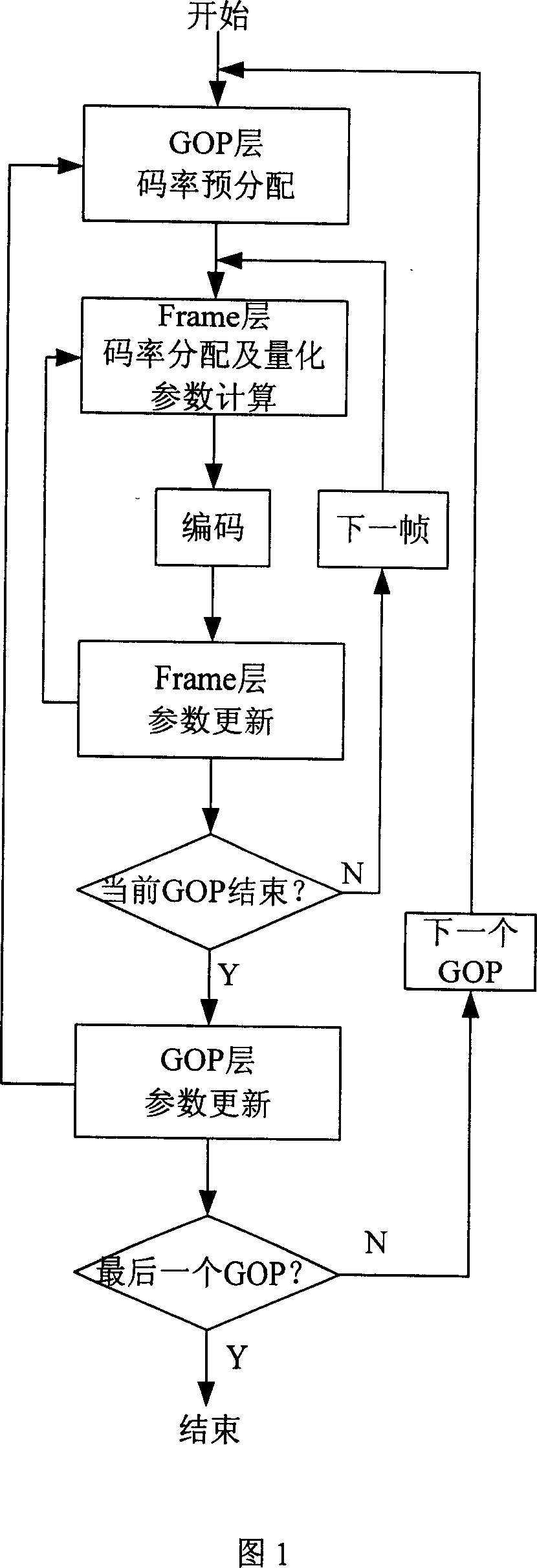
[0071] A kind of video coding code rate control method embodiment that the present invention proposes, specifically comprises the following steps:

[0072] 1): GOP layer code rate pre-allocation

[0073] (11) The encoding code rate B of the present embodiment is 80kbps, and the frame rate F is 30 frames per second, and the GOP length N gop is 15, and the value of parameter m is 3; R prev Indicates the remaining code rate or overrun code rate after the end of the previous GOP encoding. If the current GOP is the first GOP of the video sequence, then R prev The initial value is zero.

[0074] (12) If the current GOP is the last GOP of the video sequence, then the GOP pre-allocated code rate R is directly determined by the following formula:

[0075] R = B F N gop + R prev

[0076] (13) Otherwise, if | R...


PUM


Abstract

The invention relates to a method for rate control of video coding, which includes: it allocates the surplus or overruns bit to the follow-up GOP in the controlling method for the GOP layer rate. It sets the quantitative parameters in accordance with the image complexity and pre-bit-rate allocation of I frame to make the use of resources more rationally and effectively in frame-rate controlling method. It controls the quantitative parameters of the current P frames to contain the serious downward trend of P Frame encoding quality due to lack of residual rate when GOP P frame coding rapidly decline.

Description

technical field [0001] The invention belongs to the technical field of video coding, in particular to a video coding control method. Background technique [0002] Rate control is one of the important technologies of video coding, which plays an important role in applications such as video storage and transmission. For communication systems with limited bit rate, especially low bit rate, bit rate control is particularly important, which will directly determine the quality of video coding. In the currently existing video coding rate control methods, it mainly consists of three levels of rate control at the GOP-Group of picture (GOP-Group of picture) layer, frame (Frame) layer and basic unit (BU-Basic unit,) layer. . The specific steps of the code rate control method are: first at the GOP layer: pre-allocate code rates for each GOP; at the Frame layer: redistribute the code rates obtained by the GOP distribution to each frame image in each GOP, and determine for each frame im...

Claims


Application Information

Patent Timeline
IPC IPC(8): H04N7/24H04N7/26H04N19/61H04N19/82
Inventor 陆建华余成伟
Owner TSINGHUA UNIV
Why Eureka
Try Eureka