Chuck mechanism for dental handpiece and dental handpiece using the mechanism

a technology of chuck mechanism and dental handpiece, which is applied in the field of chuck mechanism, can solve the problems that the elastic function of the lock member cannot be adequately exerted, and the device may not be suitable for a dental handpiece, and achieve the effect of reducing axial runout (deflection of the axial center)

Active Publication Date: 2018-06-26
MORITA MFG CO LTD
View PDF8 Cites 0 Cited by
  • Summary
  • Abstract
  • Description
  • Claims
  • Application Information

AI Technical Summary

Benefits of technology

[0014]The object of the present invention is to provide a chuck mechanism for a dental handpiece which can adequately exert elastic chuck function and can reduce axial runout (deflection of axial center) caused by the rotor at a holding part of the rotary tool and further to provide a dental handpiece using the mechanism.
[0021]According to the present invention, the columnar rotary tool is axially rotatably held at the head part connected to the hand-held piece body by the chuck mechanism of the present invention. The rotary drive portion is embedded in the hand-held piece body, rotary power from the rotary drive portion is transmitted by the rotation transmitting portion, the rotary power is obtained from the rotation transmitting portion, then the rotary tool axially rotates with the rotor. The chucking pawl of the chucking member constituting the chuck mechanism is elastically locked in the locking groove formed at the base end part of the rotary tool which is inserted into the rotor, so that the rotary tool is prevented from being removed. The chucking pawl is provided at the elastic chucking piece axially extending from the cylindrical base part externally fitted and integrated to the rotor, the elastic chucking piece is elastically deformed against the elastic force by operating the chuck release means, and the chucking pawl can be disengaged from the locking groove. Thereby the rotary tool can be removed from the rotor, so that the elastic deformation of the elastic chucking piece is not limited in space and elastic chucking function can be adequately exerted. In addition, the cylindrical base part of the chucking member is externally fitted and integrated to the rotor, so that the circumscribed length of the rotor along the axial direction to the rotary tool can be widely secured, thereby reducing axial runout of the rotor and the rotary tool. Therefore, abrasion caused by friction of the rotor and the rotary tool is reduced, and it hardly happens that abrasion powder is accumulated and solidified between the rotor and the rotary tool and the rotary tool cannot be removed when the hand-held piece is used for a long time. In addition, when the axial runout of the rotary tool becomes small, pain caused by intermittent contact between a tooth and the rotary tool in the process of tooth cutting cut can be reduced, thereby relieving a patient.
[0022]In the present invention, when most of the inner circumference of the rotor is circumscribed with the shank part of the rotary tool while the rotary tool is inserted into the rotor, the circumscribed length of the rotor to the shank part can be widely secured, thereby further effectively reducing the axial runout. When the portion other than the chucking pawl and its vicinity of the chucking member is externally fitted to the rotor, the circumscribed length of the rotor to the shank part can also be widely secured.
[0023]In the present invention, when a pair of the elastic chucking pieces are axisymmetrically provided and are elastically deformable in the radial direction to the axial center of the rotary tool, a pair of the chucking pawls can be locked in the locking groove so as to sandwich the base end part of the rotary tool. Therefore, the non-removable state of the rotary tool can be stably kept by such locking. In addition, the elastic chucking pieces are provided axisymmetrically, so that the force applied on the rotary tool along the radial direction can be uniform, thereby further reducing the axial runout.
[0024]In the present invention, the tubular rotor outer member which is externally fitted and integrated to the cylindrical base part of the chucking member can be further provided and the base part of the rotary tool can be engaged with the rotor outer member so as not to be rotatable each other. In this case, the chucking member and the rotor are integrated and the chucking member and the rotor outer member are also integrated, thereby the rotor and the rotor outer member become integrated. In addition, the rotary tool is engaged with the rotor outer member so as not to be rotatable each other, thereby the rotary force of the rotor is transmitted to the rotary tool via the chucking member and the rotor outer member. In this case, when the bearing for rotatably attaching the rotor to the head part is fitted and attached at the outer circumference of the rotor outer member, space required for the chuck mechanism in the head part can be reduced. In addition, when a portion of the rotor outer member to which the bearing is fitted corresponds to a locking part of the chucking pawl of the chucking member and the locking groove of the rotary tool, the space can be further reduced, thereby reducing bulk of the head part in the axial direction and keeping suitability as a dental handpiece which is used to be inserted into narrow oral cavity.

Problems solved by technology

In the embodiment, it is pointed out as a problem that elastic function of the lock member cannot be adequately exerted even when the lock member is designed to be able to elastically ream (enlarge) in a limited space.
The chuck device disclosed in PTL 1 as a new invention adequately exerts elastic function of the lock member; however, the head part becomes bulky in the axial center direction of the bar tube because the chuck device is positioned on the upper part of the upper bearing, so that such a device may not be suitable for a dental handpiece which is used to be inserted into narrow oral cavity.

Method used


Image

  • Chuck mechanism for dental handpiece and dental handpiece using the mechanism
  • Chuck mechanism for dental handpiece and dental handpiece using the mechanism
  • Chuck mechanism for dental handpiece and dental handpiece using the mechanism

Examples


Embodiment Construction

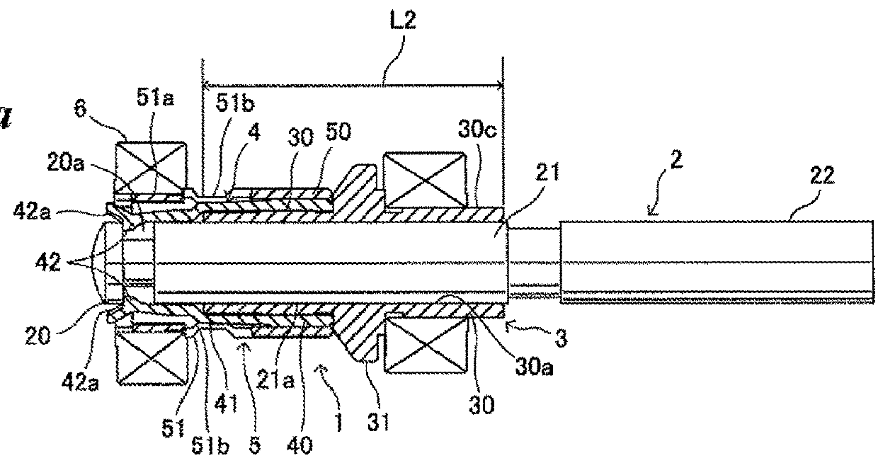
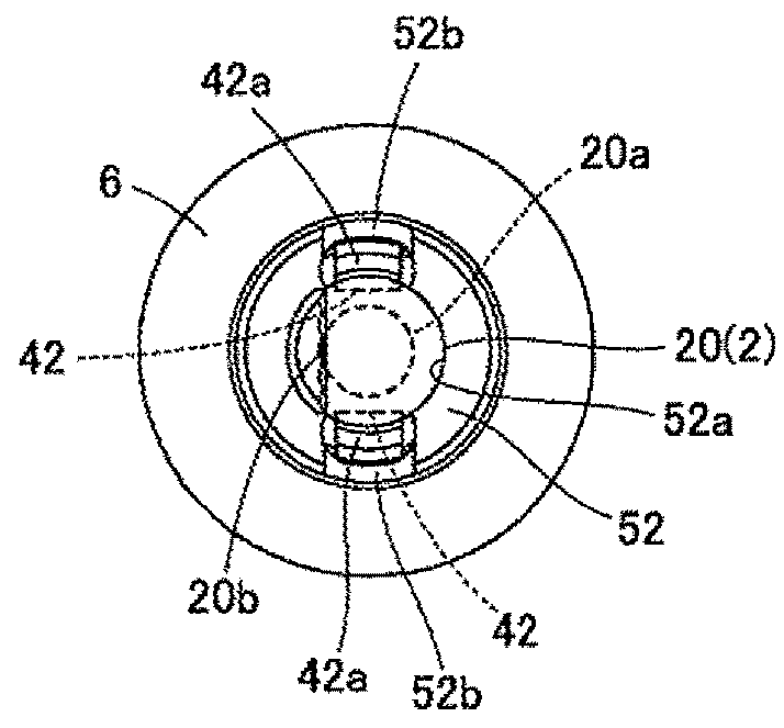
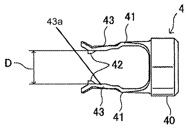
[0040]The embodiments of a chuck mechanism for a dental handpiece and a dental handpiece using the mechanism according to the present invention are explained based on the drawings. In the chuck mechanism 1 shown in FIG. 1a, a tubular rotor 3 is externally fitted to a shank part 21 of a rotary tool (a contra-bar or a latch bar) 2. The rotor 3 has a tool guide tube part 30 to which the shank part 21 of the rotary tool 2 is inserted so as to be held along the entire length and an inner circumference 30a of the tool guide tube part 30 circumscribes with the shank part 21 of the rotary tool 2. The circumscribed length is represented as L2. The chuck mechanism 1 has a chucking member 4 as shown in FIG. 1b and FIG. 1c. The chucking member 4 has a cylindrical base part 40 which is externally fitted to and integrated with an outer circumference 30b of the tool guide tube part 30 on the side of a base end part 20 of the rotary tool2 (called outer circumference on the base end side, hereinafte...


PUM


Abstract

A chuck mechanism for a dental handpiece holds a columnar rotary tool for dental care rotatably with an annular rotor of the dental handpiece. The columnar rotor tool is concentrically detachable to the annular rotor which is rotatably attached to a head part of the dental handpiece. The chuck mechanism has an annular chucking member with a cylindrical base part into which the annular rotor is integrally fitted and an elastic chucking piece having a chucking pawl for engaging with a locking groove formed at a base end of the rotary tool. The chuck mechanism enables the rotary tool to be easily removed from the annular rotor by elastically deforming the elastic chucking piece against elastic force of the elastic chucking piece to disengage the chucking pawl from the locking groove.

Description

CROSS REFERENCE TO RELATED APPLICATIONS[0001]This application claims the benefit of priority under 35 USC 119 of Japanese application no. 2011-012914, filed on Jan. 25, 2011, and Japanese application no. 2011-144326, filed on Jun. 29, 2011.BACKGROUND OF THE INVENTION[0002]Technical Field[0003]The present invention relates to a chuck mechanism for detachably holding a rotary tool at a head part of a dental handpiece, specifically a micro-motor hand-held piece and further to a dental handpiece using the chuck mechanism.[0004]Background Art[0005]A dental micro-motor hand-held piece is designed such that a columnar rotary tool for cutting teeth (called contra-bar or latch bar) is detachably attached on a head part and axially rotates by rotary drive force of a micro-motor (rotary drive portion) embedded in the hand-held piece body. Several kinds of rotary tools are prepared and a suitable one is selected from them by an operator depending on the state of affected region and is used by a...

Claims


Application Information

Patent Timeline
Patent Type & Authority Patents(United States)
IPC IPC(8): A61C1/14
CPCA61C1/141A61C1/144A61C1/142
Inventor TANAKA, HITOSHIONO, HIROYUKINAKAYAMA, SHOZO
Owner MORITA MFG CO LTD
Why Eureka
Try Eureka