Surgical stapling loading unit with stroke counter and lockout

a technology of loading unit and surgical stapler, which is applied in the field of surgical staples, can solve the problems of high cost of single surgical procedure use of additional surgical staplers

Active Publication Date: 2018-08-14
TYCO HEALTHCARE GRP LP
View PDF1429 Cites 656 Cited by
  • Summary
  • Abstract
  • Description
  • Claims
  • Application Information

AI Technical Summary

Problems solved by technology

The use of additional surgical staplers for a single surgical procedure can be expensive.

Method used


Image

  • Surgical stapling loading unit with stroke counter and lockout
  • Surgical stapling loading unit with stroke counter and lockout
  • Surgical stapling loading unit with stroke counter and lockout

Examples


Embodiment Construction

[0049]Particular embodiments of the present disclosure are described hereinbelow with reference to the accompanying drawings; however, it is to be understood that the disclosed embodiments are merely examples of the disclosure and may be embodied in various forms. Well-known functions or constructions are not described in detail to avoid obscuring the present disclosure in unnecessary detail. Therefore, specific structural and functional details disclosed herein are not to be interpreted as limiting, but merely as a basis for the claims and as a representative basis for teaching one skilled in the art to employ the present disclosure in virtually any appropriately detailed structure.

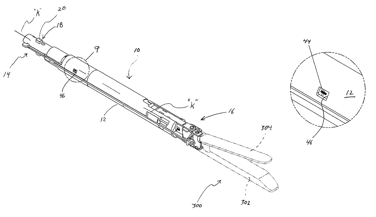
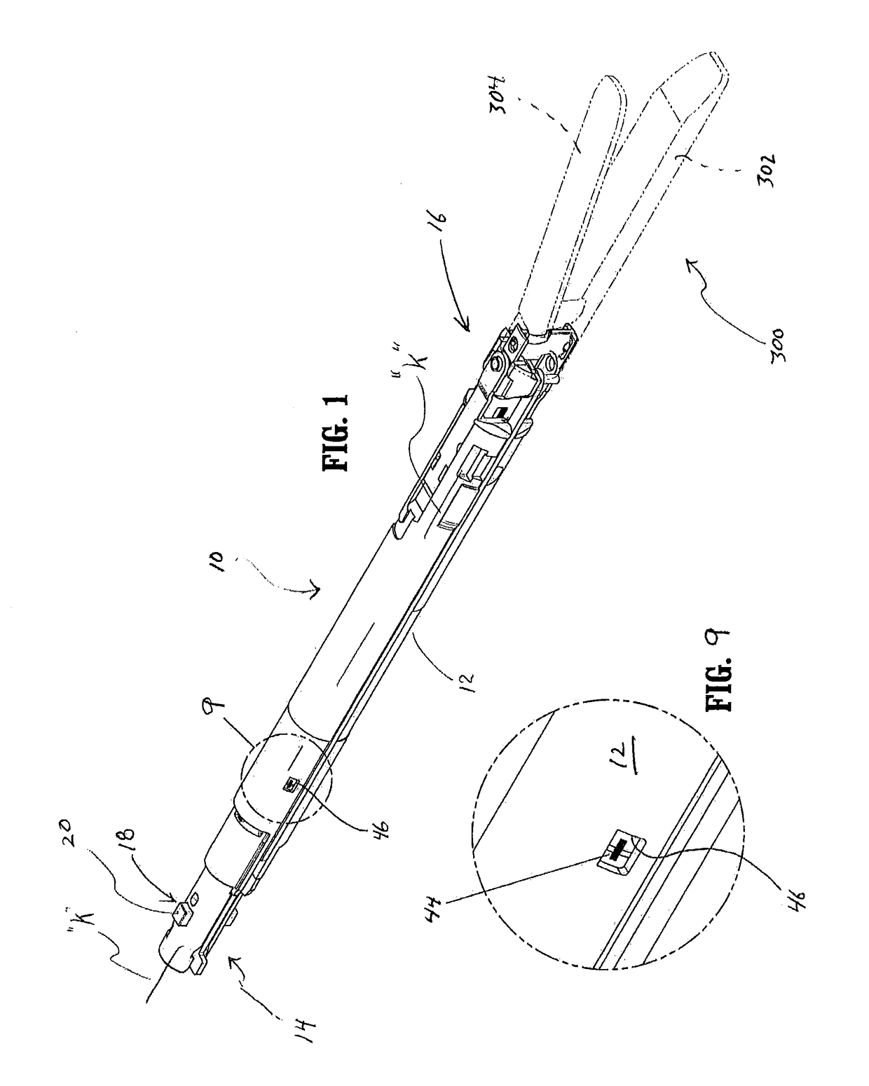
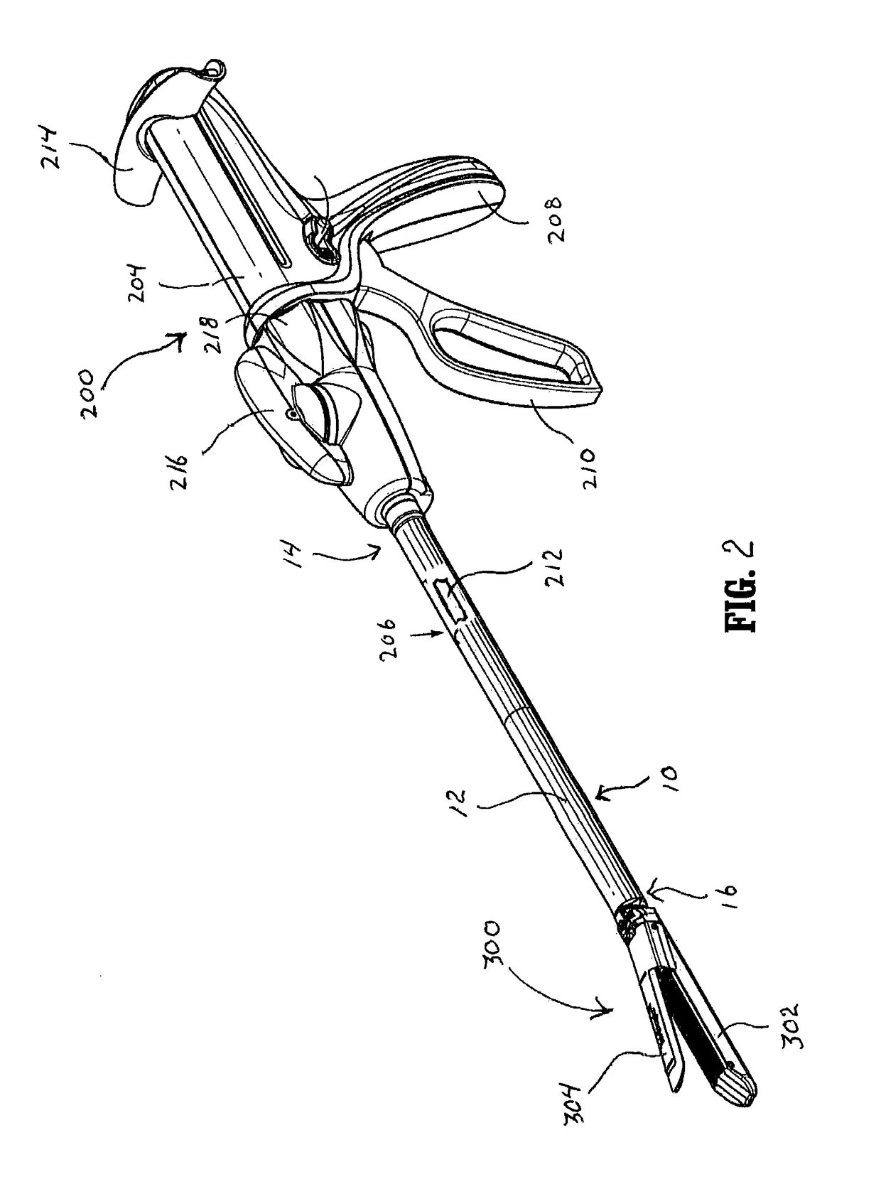
[0050]Referring now to the drawings where like reference numerals indicate similar components throughout the several views, FIGS. 1-2 illustrate the surgical loading unit 10 in accordance with the principles of the present disclosure. In FIG. 1, the surgical loading unit 10 is depicted in isolation while...


PUM


Abstract

A surgical loading unit for use with a handle assembly includes an elongate outer frame, an end effector mounted to a distal end of the outer frame, a drive at least partially disposed within the outer frame and operatively coupled to the end effector, and a rotatable counter mounted to the outer frame and adapted for rotational movement about the longitudinal axis. A counter actuator is mounted to the drive and dimensioned to engage the rotatable counter to cause rotational movement of the rotatable counter through an arc segment of rotation during each firing stroke of the drive.

Description

BACKGROUND[0001]1. Technical Field[0002]The present disclosure relates to a surgical stapling apparatus, and more particularly, relates to a surgical stapling loading unit having a firing stroke counter and a lockout which locks the loading unit upon completion of a predefined number of firing strokes.[0003]2. Background of Related Art[0004]Surgical staplers for stapling tissue are known in the art and are inclusive of both single use and multiple use devices. Single use devices are preloaded with one or more staples and are disposed after a single use. Multiple use devices are disposed upon exhaustion of the supply of staples or completion of the surgical procedure. If the supply of staples is exhausted prior to completion of a surgical procedure, a new surgical stapler may be required to complete the surgical procedure. The use of additional surgical staplers for a single surgical procedure can be expensive.[0005]In order to address the high expense associated with the use of mult...

Claims


Application Information

Patent Timeline
Patent Type & Authority Patents(United States)
IPC IPC(8): A61B17/068A61B17/072A61B17/10A61B17/00A61B90/00
CPCA61B17/105A61B17/068A61B17/07207A61B2090/0814A61B2090/0803A61B2090/0807A61B2017/00473
Inventor MURTHY ARAVALLI, AVVLN SRINIVASA
Owner TYCO HEALTHCARE GRP LP
Why Eureka
Try Eureka