Utility knife assembly with two blades

a technology of utility knife and blade, which is applied in the direction of cross-cut saws, pad saws, manufacturing tools, etc., can solve the problems of inconvenient for some users and hurt users, and achieve the effect of easy pivoted ou

Active Publication Date: 2018-12-11
CHEN YI JHEN
View PDF29 Cites 3 Cited by
  • Summary
  • Abstract
  • Description
  • Claims
  • Application Information

AI Technical Summary

Benefits of technology

[0012]The primary object of the present invention is to provide a utility knife assemb...

Problems solved by technology

Once the friction fails to maintain the blade at positions, the blade may unexpec...

Method used


Image

  • Utility knife assembly with two blades
  • Utility knife assembly with two blades
  • Utility knife assembly with two blades

Examples


Embodiment Construction

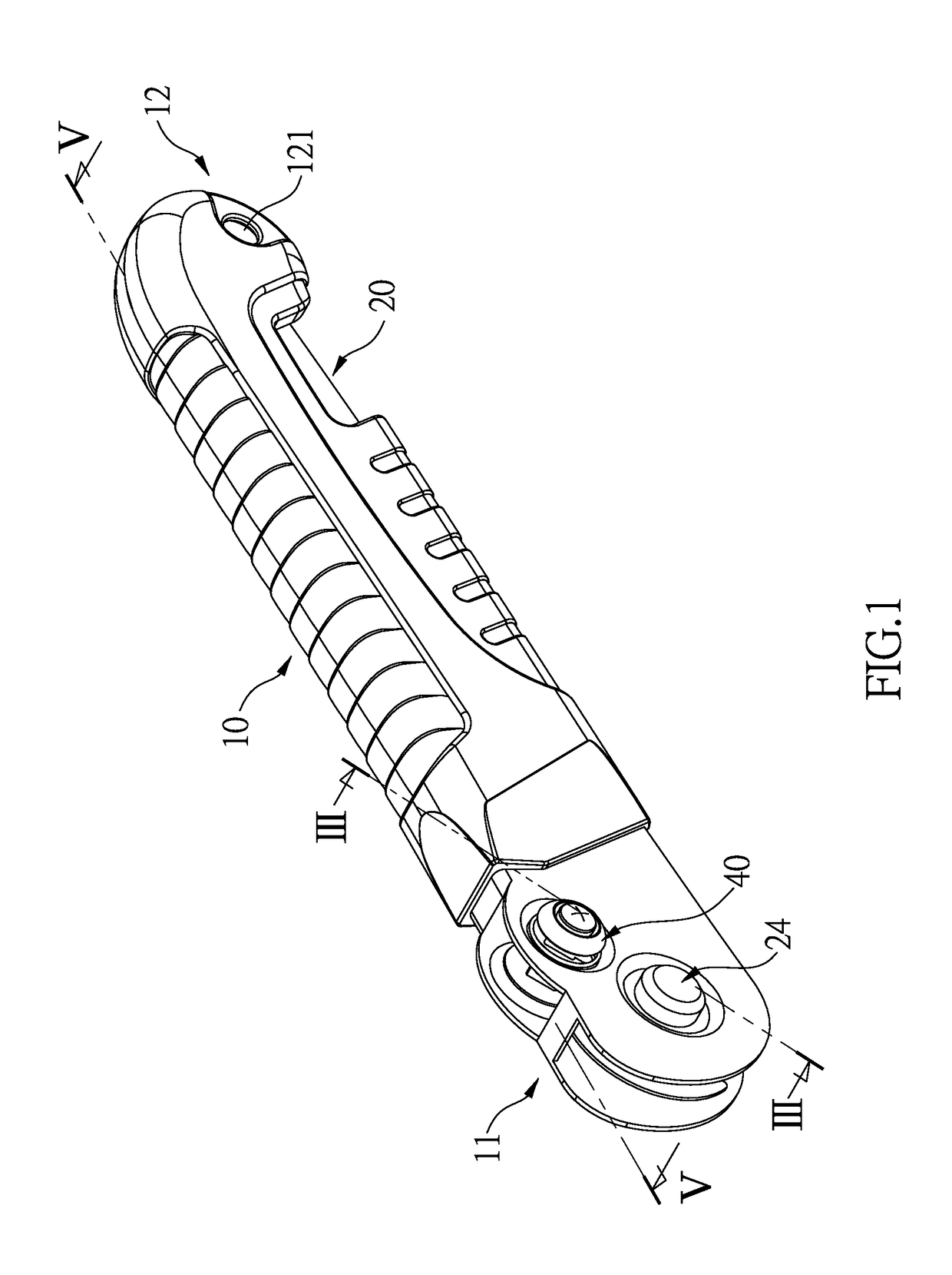
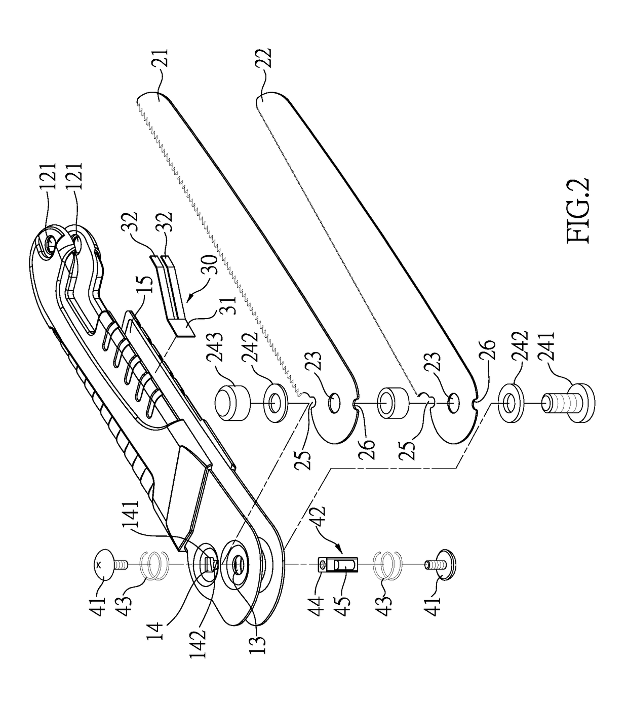
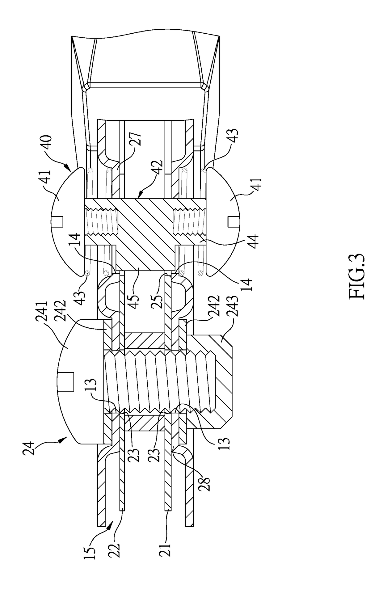
[0022]Referring to FIGS. 1 to 3, the utility knife assembly of the present invention comprises a case 10 composed of two symmetrical parts, and a pivotal end 11 and a hanging end 12 are respectively formed on two ends of the case 10. The pivotal end 11 includes a pivotal hole 13 and a fixing hole 14 respectively defined therethrough. A hanging hole 121 is defined through the hanging end 12 of the case 10, such that the case 10 can be hanged on a hook or a rod on a wall. A rope may also be extended through the hanging hole 121 to attach the case 10 to a protrusion. A slot 15 is defined axially in the case 10 and communicates with the fixing hole 14 and the pivotal hole 13. The slot 15 extends from the pivotal end 11 toward the hanging end 12.

[0023]A blade unit 20 includes a first blade 21 and a second blade 22, and the first and second blades 21, 22 are received in the slot 15 in parallel. Each of the first and second blades 21, 22 has an aperture 23 defined through the first end the...


PUM


Abstract

A utility knife assembly includes a case having a slot in which two blades are received. A resilient plate is secured in the slot and includes two resilient fingers to push the blades out from the slot. A switch unit is connected to the case and selectively activates either one of the two blades to be pivoted out from the slot.

Description

BACKGROUND OF THE INVENTION1. Fields of the Invention[0001]The present invention relates to a utility knife assembly, and more particularly, to a utility knife assembly with two blades.2. Descriptions of Related Art[0002]The conventional utility knife assembly generally includes a case with a slot, and a blade is pivotably connected to the case and received in the slot. The blade is pivotable relative to the slot. A bolt extends through the case and one end of the blade so as to connect the blade. Friction between the bolt, the blade and the hole in blade provide a restriction feature to keep the blade to be positioned at a position. Once the friction fails to maintain the blade at positions, the blade may unexpectedly drop out from the slot and may hurt the users.[0003]When the blade is received in the slot of the case, the back of the blade slightly protrudes beyond the slot so that the users have to use fingers to pull the blade out from the slot when in use. This is inconvenient...

Claims


Application Information

Patent Timeline
IPC IPC(8): B26B9/02B26B1/04
CPCB26B1/044B26B9/02B26B1/046B26B3/04B27B21/04B23D49/003B23D51/01
Inventor CHEN, YI JHEN
Owner CHEN YI JHEN
Why Eureka
Try Eureka