Light source device and display apparatus

a technology of light source and display apparatus, which is applied in the direction of optics, instruments, optical light guides, etc., can solve the problems of reflection sheet, uneven luminance or insufficiency of luminance on the display surface, and deterioration of the so as to improve incidence efficiency and high reflection efficiency , the effect of high display quality of the display apparatus

Inactive Publication Date: 2019-01-01
SAKAI DISPLAY PROD
View PDF3 Cites 2 Cited by
  • Summary
  • Abstract
  • Description
  • Claims
  • Application Information

AI Technical Summary

Benefits of technology

[0040]According to the embodiment of the present invention, the possibility of the reflection sheet touching the light source can be eliminated, and it is possible to maintain high reflection efficiency at the one broad surface of the light guide plate. Enough space is provided around the light source to thereby have a tolerance for position both of the light source and the light guide plate. In addition, by providing the reflection member in the space, it is possible to improve incidence efficiency from the light source to the light guide plate, and maintain high display quality of the display apparatus with the light source device.

Problems solved by technology

The extension of the reflection sheet due to the thermal expansion causes the reflection sheet to wrinkle or bend, which may cause deterioration in the display quality of the display apparatus such as uneven luminance or insufficiency of luminance on the display surface.
In the case that the reflection sheet is configured to be supported by a support at a light-source-side end part, the reflection sheet is restricted in extension by the support, and is thus highly likely to wrinkle or bend.
This may cause curling of the reflection sheet at its end part and an unwanted clearance between the reflection sheet and the light guide plate.
Furthermore, in this case, if the end part light source of the reflection sheet is protruded longer than the side surface of the light guide plate, the protruding portion is made closer to the light source and expands due to more heat, which may raise the possibility of the end part of the reflection sheet touching the light source.
In the case that the end part of the reflection sheet touches the light source and deviates to be escaped from the light source, a clearance appears between the reflection sheet and the light guide plate, which may cause in the deterioration of reflection efficiency of the reflection sheet.
Moreover, in the case that the end part of the reflection sheet touches the light source and covers a part of the light source, a light leakage occurs.
The deterioration of the reflection efficiency and the occurrence of the light leakage may cause degradation in the display quality such as uneven luminance or luminance degradation.

Method used


Image

  • Light source device and display apparatus
  • Light source device and display apparatus
  • Light source device and display apparatus

Examples


embodiment 1

[0050](Embodiment 1)

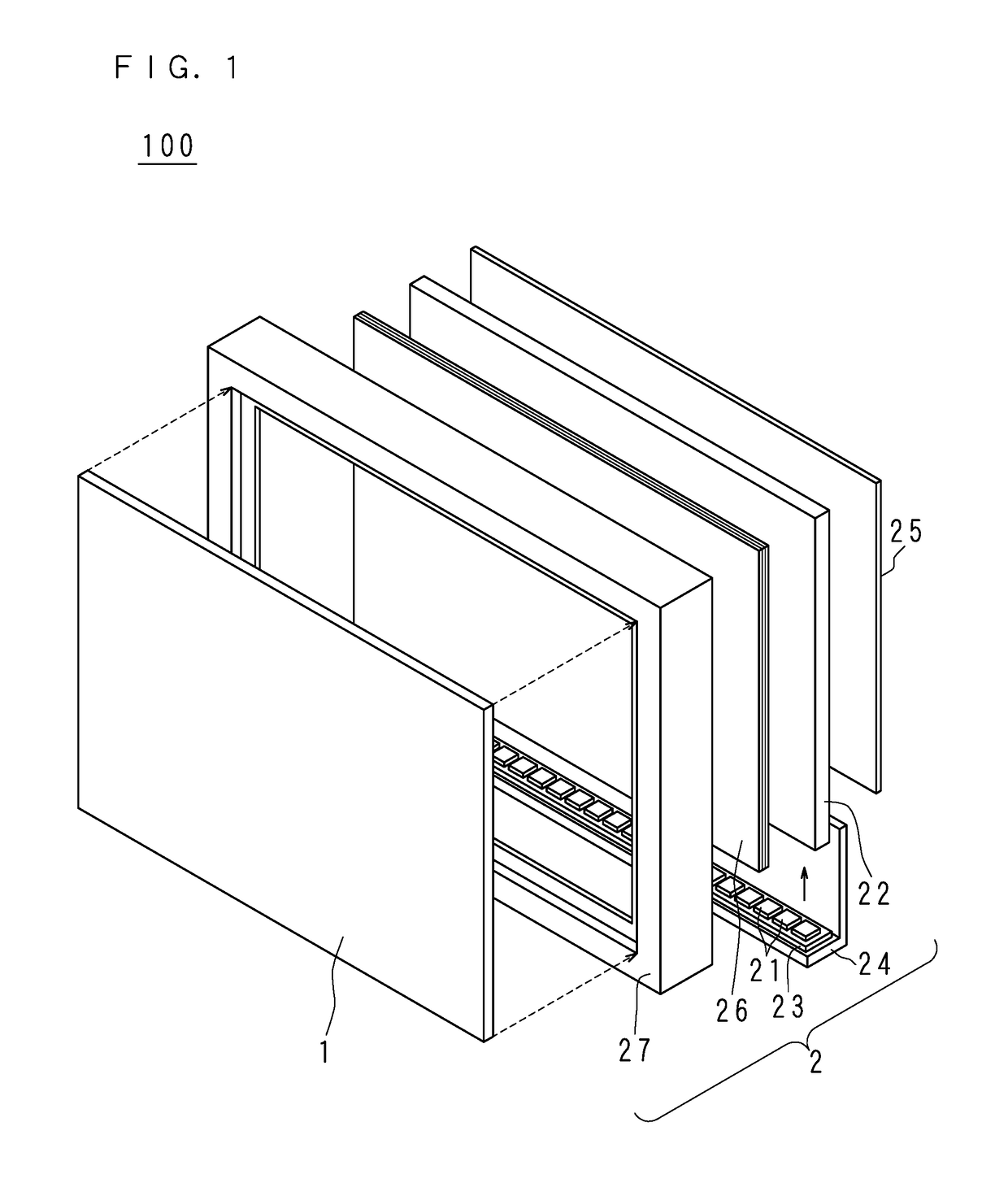
[0051]FIG. 1 is an exploded perspective view schematically illustrating main components included in a display apparatus 100 according to Embodiment 1. The display apparatus 100 comprises a liquid crystal panel 1 and a light source device 2.

[0052]The liquid crystal panel 1 is a display panel, and is formed in a rectangular plate shape. The liquid crystal panel 1 employs an active matrix type. The liquid crystal panel 1 is configured by sealing liquid crystal between two transparent substrates arranged to face each other with a prescribed distance between them.

[0053]The light source device 2 is an edge light type device utilizing a light emitting diode 21 as a light source, and comprises the light emitting diode 21, a light guide plate 22, a substrate 23, a heat dissipation plate 24, a reflection sheet 25, an optical sheet 26 and a chassis 27.

[0054]The light emitting diode 21 is a light emitting element that emits white light, which is achieved by applying a phosph...

embodiment 2

[0083](Embodiment 2)

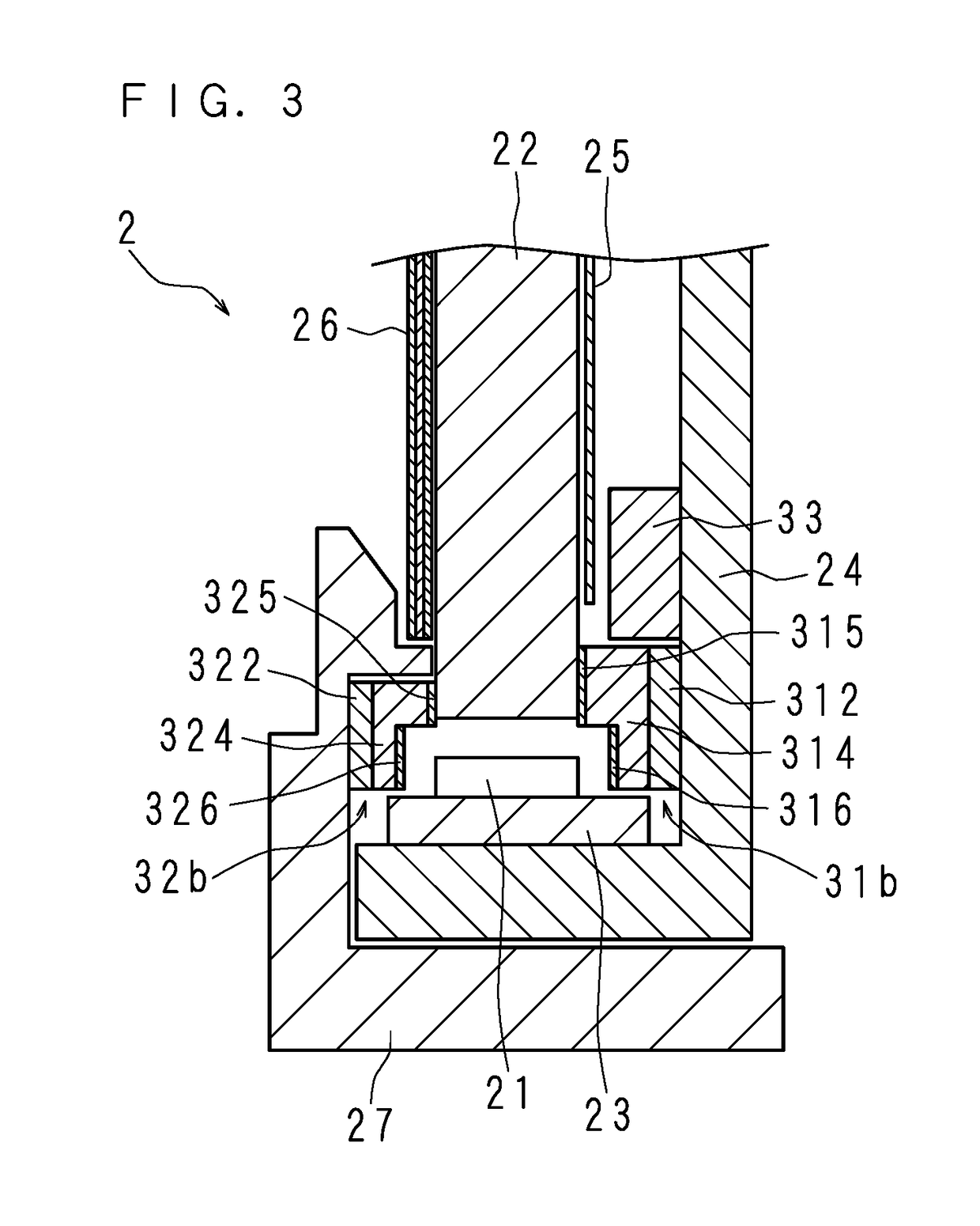
[0084]FIG. 3 is a section view schematically illustrating a light source device 2 according to Embodiment 2. A configuration of the light source device 2 according to Embodiment 2 is similar to the configuration according to Embodiment 1 other than the configuration of the light leakage prevention unit. Therefore, the configuration equivalent to Embodiment 1 will be denoted by the same reference numerals, and will not be described in detail.

[0085]FIG. 3 schematically illustrates an enlarged section of an end part of the light source device 2 proximal to the light emitting diode 21 according to Embodiment 2. In Embodiment 2, a first light leakage prevention unit 31b filling a space is provided between the facing planes of the exposed surface of the light guide plate 22 and the heat dissipation plate 24.

[0086]As shown in FIG. 3, the first light leakage prevention unit 31b according to Embodiment 2 comprises a base body 314 being stepped in cross section on the ligh...

embodiment 3

[0093](Embodiment 3)

[0094]FIG. 4 is a section view schematically illustrating a light source device 2 according to Embodiment 3. A configuration of the light source device 2 according to Embodiment 3 is similar to the configuration according to Embodiment 1 other than the configuration of the light leakage prevention unit and the detailed configuration of the chassis 27. Therefore, the configuration equivalent to Embodiment 1 will be denoted by the same reference numerals, and will not be described in detail.

[0095]FIG. 4 schematically illustrates an enlarged section of an end of the light source device 2 proximal to the light emitting diode 21. In Embodiment 3, a first light leakage prevention unit 31c filling in a space is provided between the facing planes of the exposed surface of the light guide plate 22 and the heat dissipation plate 24.

[0096]The first light leakage prevention unit 31c according to Embodiment 3 comprises a spacer 34 that is adhered and secured so as to extend a...


PUM

PropertyMeasurementUnit
distanceaaaaaaaaaa
thicknessaaaaaaaaaa
thermal expansionaaaaaaaaaa

Abstract

Provided is a light-source device comprising a light guide plate having a rectangular shape, a light source facing a side surface of the light guide plate, a reflective sheet having a rectangular shape facing one broad surface of the light guide plate, and a plate-shaped member provided at a distance from the one broad surface. The light source side edge of the reflective sheet is located inwards of a light source side edge of the light guide plate such that a part of the one broad surface on the light source side is formed as an exposed surface, and light leakage prevention unit filling the space between the exposed surface and the plate-shaped member is provided with a protruding portion protruding towards the light source. A reflective body is provided at a position corresponding to a clearance provided between the edge of the reflective sheet and the light-leakage prevention unit.

Description

[0001]This application is the national phase under 35 U.S.C. § 371 of PCT International Application No. PCT / JP2014 / 066569 which has an International filing date of Jun. 23, 2014 and designated the United States of America.BACKGROUND OF THE INVENTION[0002]1. Field of the Invention[0003]The present invention relates to a display apparatus employing a liquid crystal panel, and to a light source device capable of maintaining high display quality and a display apparatus including the light source device.[0004]2. Description of Related Art[0005]In the recent display apparatuses employing a liquid crystal panel, edge light type light source devices are commonly used for thinning the display apparatus. The edge light type light source device is configured such that a light source such as a light emitting diode and the like is arranged to oppose a side surface of a light guide plate, and light progressing from the side surface into the light guide plate is uniformly emitted from one broad su...

Claims


Application Information

Patent Timeline
Patent Type & Authority Patents(United States)
IPC IPC(8): G02F1/1335F21V8/00
CPCG02B6/0088G02B6/0023G02B6/0085G02B6/0043G02B6/0055G02B6/0031
Inventor TERAGAWA, DAISUKE
Owner SAKAI DISPLAY PROD
Why Eureka
Try Eureka