
Light guide plate, planar lighting device, and liquid crystal display device

A technology of light guide plate and light exit surface, applied in the field of light guide plate

Active Publication Date: 2013-05-22
FUJIFILM CORP
View PDF18 Cites 2 Cited by
  • Summary
  • Abstract
  • Description
  • Claims
  • Application Information

AI Technical Summary

Problems solved by technology

[0004] However, for a direct-type backlight unit, the thickness in the direction perpendicular to the liquid crystal display panel must be about 30 mm in order to make the light distribution uniform, and it is difficult to make the thickness thinner than about 30 mm.

Method used


Image

  • Light guide plate, planar lighting device, and liquid crystal display device
  • Light guide plate, planar lighting device, and liquid crystal display device
  • Light guide plate, planar lighting device, and liquid crystal display device

Examples


example 1

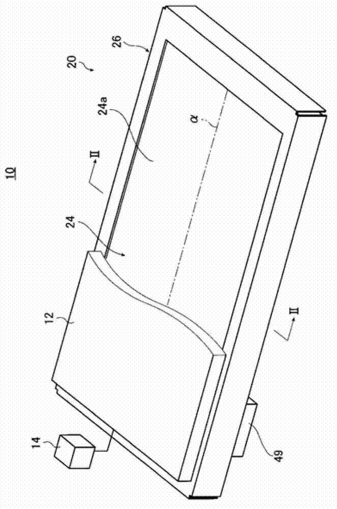
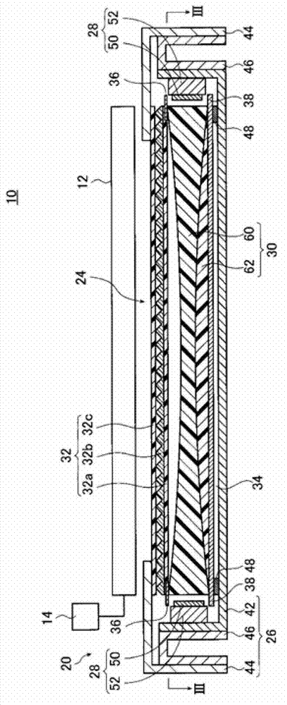
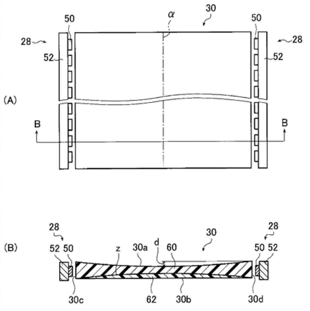
[0218]The light guide plate 30 when the screen size corresponds to 42 is used as Example 1. Specifically, a light guide plate whose length from the first light incident surface 30c to the second light incident surface 30d is set to 545 mm and whose length from the light exit surface 30a to the back surface 30b at the bisector α is The length until the length, that is, the thickness D of the thinnest part is set as 2.56mm, the thickness of the first light incident surface 30c and the second light incident surface 30d, that is, the thickness of the thickest part is set as 3.0mm, and the thickness of the first light incident surface 30c and the second light incident surface 30d is set as 3.0mm. The length from the light exit surface 30a to the boundary surface z at the bisector α of the first layer 60, that is, the thickness D1 of the first layer 60 at the thinnest part of the first layer 60 is set to 2.12 mm, and the second The length from the boundary surface z to the rear surf...

example 2

[0237] As Example 2, the following light guide plate 80 is used. This light guide plate 80 is a light guide plate with the same shape as Example 1 and a screen size of 46, such as Figure 12 As shown, the boundary surface z between the first layer 60 and the second layer 62 is such that the second layer 62 enters the first light from the light exit surface 30a (ie, the central part of the light exit surface) at the bisector α. The surface 30c and the second light incident surface 30d change continuously so that they become thinner, and continue to become thicker again toward the light exit surface 30a near the first light incident surface 30c and the second light incident surface 30d. changed. At this time, the synthetic particle concentration is obtained using the reverse deviation concentration, and the thicknesses (shape of the boundary surface z) of the first layer 60 and the second layer 62 are obtained from the obtained synthetic particle concentration.

[0238] That is...

example 3

[0250] As example 3, Figure 12 The light guide plate 80 shown is a light guide plate when the screen size is 32, and the curvature radius R of the concave and convex curved surfaces of the boundary surface z is changed y1 , R y2 , and the particle concentrations of the first layer 60 and the second layer 62 are measured.

[0251] Specifically, the following light guide plate is used as Example 3. The length of the light guide plate from the first light incident surface 30c to the second light incident surface is set to 413mm, and the first light incident surface 30c and the second light incident surface 30d The thickness, that is, the thickness D2 of the thickest part is set to 3mm, the amount of depression d is set to 0.5mm, the radius of curvature of the light exit surface 30a is set to 42500mm, and the thickness D3 of the second layer 62 on the first light incident surface The thickness D4 of the thinnest part of the second layer 62 was 0.5 mm, and the thickness D5 of th...


PUM

PropertyMeasurementUnit
radiusaaaaaaaaaa
particle diameteraaaaaaaaaa
radiusaaaaaaaaaa

Abstract

In order to provide a light guide plate which has high light utilization efficiency and can emit light having less unevenness of luminance, and in which the a part near the center of a screen has a brighter distribution than that in a peripheral part of the screen, scattering particles are multi-dispersed particles produced by mixing particles having different particle diameters, the light guide plate has at least two layers which are overlied on each other in the direction almost perpendicular to the light output surface and contain the scattering particles at different particle concentrations, the at least two layers comprise a first layer which has a particle concentration of Npo and is arranged on the light output surface side and a second layer which has a particle concentration of Npr and is arranged on the backward side relative to the firs layer, Npo and Npr meet the relationship represented by the formula Npo < Npr, the cross section of the light guide plate on the light output surface side has a concaved shape when the cross section is taken in the direction perpendicular to the light incident surface, and the thicknesses of the first layer and the second layer are changed in the direction almost perpendicular to the light output surface so as to change the concentration of the synthetic particles in a part of the light guide plate which corresponds to the concentration-changed layers.

Description

technical field [0001] The present invention relates to a light guide plate used in liquid crystal display devices and the like. Background technique [0002] A liquid crystal display device uses a backlight unit that emits light from the back side of a liquid crystal display panel (panel) to illuminate the liquid crystal display panel. The backlight unit is constituted by components such as a light guide plate, a prism sheet, or a diffusion sheet. The light emitted from the light guide plate is uniform. [0003] Currently, a so-called direct-type method in which a light guide plate is arranged directly above a light source for illumination is the mainstream for a backlight unit of a large-sized liquid crystal television (television). In this method, a plurality of cold cathode tubes as light sources are arranged on the back of the liquid crystal display panel, and the interior is set as a white reflective surface to ensure uniform light distribution and necessary shell de...

Claims


Application Information

Patent Timeline
Patent Type & Authority Applications(China)
IPC IPC(8): F21S2/00F21V8/00G02F1/13357F21Y101/02
CPCG02B6/0051G02B6/0046G02B6/0088G02B6/005G02B6/0041G02B6/0053G02F1/133606
Inventor 岩崎修
Owner FUJIFILM CORP
Learn More