
Backlight unit including COB type light emitting diode module

a diode module and backlight technology, applied in the field of backlight units, can solve the problems of inefficient design of the connection structure between the led module and the display panel, and achieve the effects of improving the connection structure, reducing the outer thickness of the blu, and increasing the incidence efficiency of light emitted

Active Publication Date: 2015-02-24
SAMSUNG ELECTRONICS CO LTD
View PDF29 Cites 2 Cited by
  • Summary
  • Abstract
  • Description
  • Claims
  • Application Information

AI Technical Summary

Benefits of technology

This patent describes a way to make a thin backlight for electronic devices by using a special light emitting diode (LED) module which is placed on a circuit board. The LED module is designed to emit light in a way that maximizes its efficiency. Additionally, the patent also describes how to improve the connection between the LED module and a light guide panel, which helps to increase the amount of light that is emitted. This invention helps to make electronic devices brighter and more energy-efficient.

Problems solved by technology

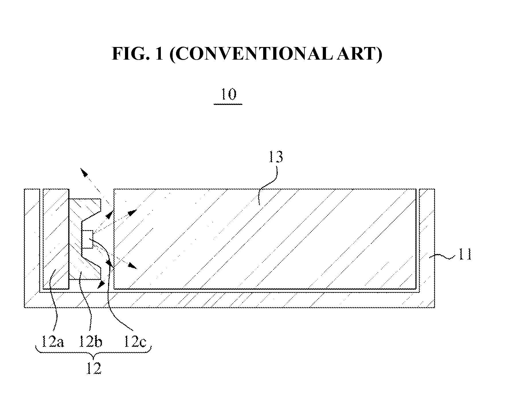
By using a packaged LED, the connection structure between the LED module and the display panel may be inefficiently designed.

Method used


Image

  • Backlight unit including COB type light emitting diode module
  • Backlight unit including COB type light emitting diode module
  • Backlight unit including COB type light emitting diode module

Examples


Embodiment Construction

[0041]Reference will now be made in detail to example embodiments, examples of which are illustrated in the accompanying drawings, wherein like reference numerals refer to the like elements throughout. In the following description, when it is determined that a detailed description of well-known functions related to the present invention and the construction thereof would make the gist of the present invention obscure, they will be omitted.

[0042]Detailed illustrative embodiments are disclosed herein. However, specific structural and functional details disclosed herein are merely representative for purposes of describing example embodiments. Example embodiments may be embodied in many alternate forms and should not be construed as limited to only those set forth herein.

[0043]It should be understood, however, that there is no intent to limit this disclosure to the particular example embodiments disclosed. On the contrary, example embodiments are to cover all modifications, equivalents,...


PUM

PropertyMeasurementUnit
conductiveaaaaaaaaaa
transparentaaaaaaaaaa
electrical characteristicsaaaaaaaaaa

Abstract

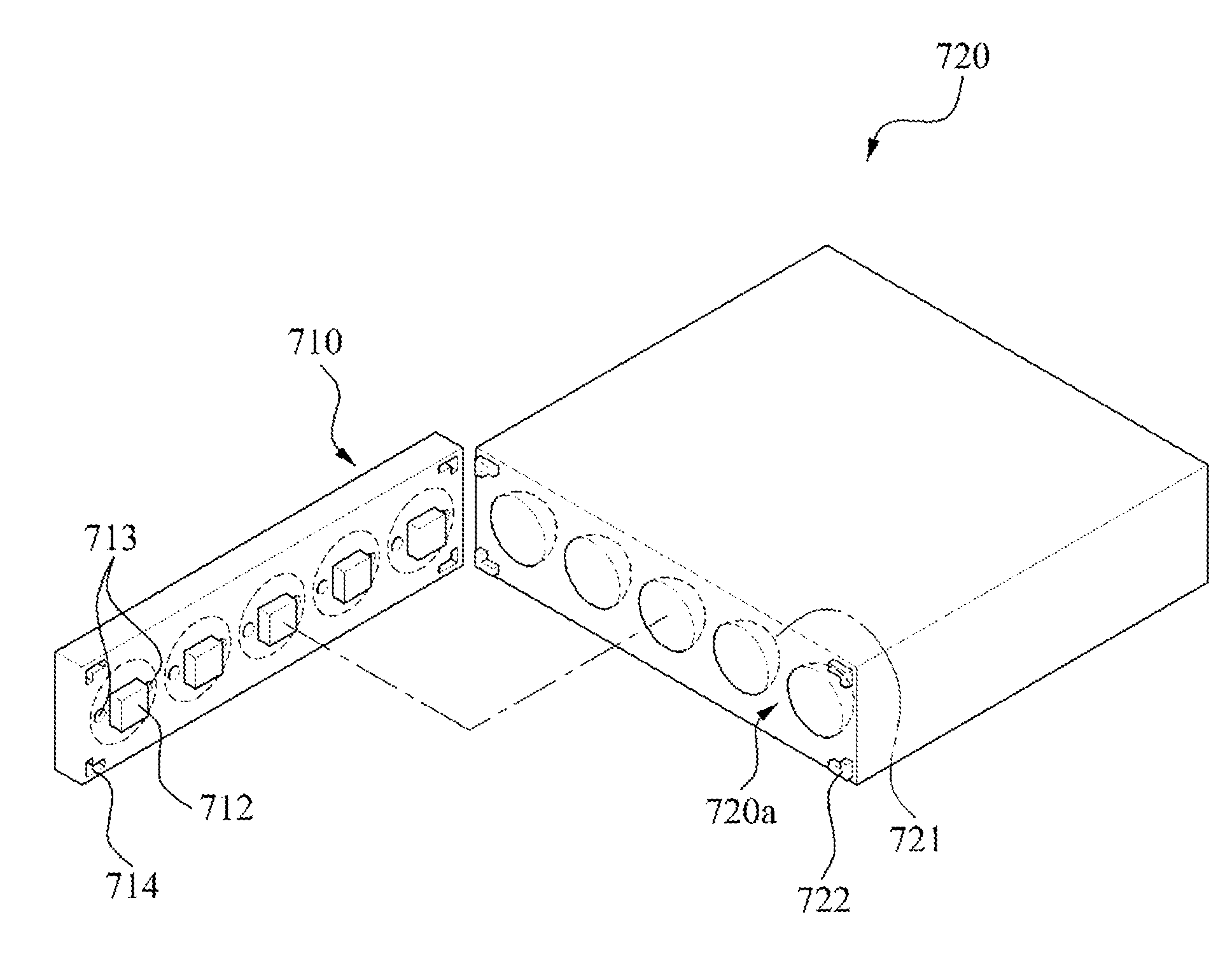
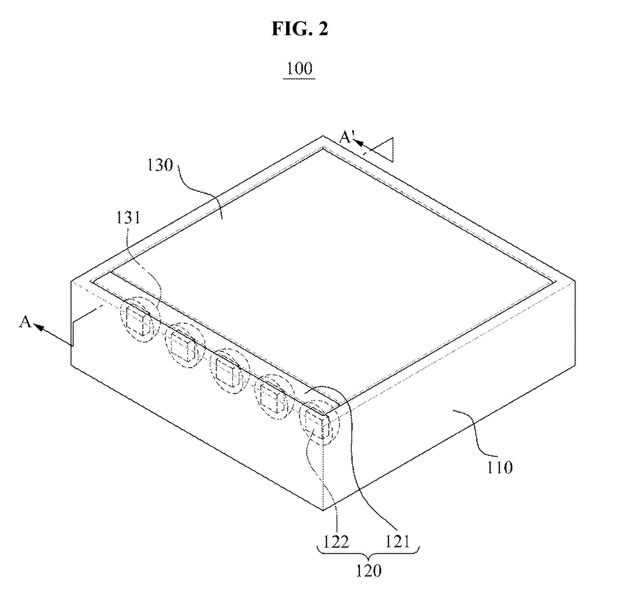
A backlight unit (BLU) is disclosed. The BLU may include a light emitting diode (LED) module including at least one LED chip mounted on a substrate in a chip-on-board (COB) type, and a light guide panel including an incidence surface configured to receive light emitted from an emission surface of the LED chip and to include at least one insertion recess disposed corresponding to the LED chip, such that the LED chip is bonded to the LED module to be inserted in the insertion recess.

Description

CROSS-REFERENCE TO RELATED APPLICATION[0001]This application claims the benefit of Korean Patent Application No. 10-2011-0084894, filed on Aug. 25, 2011, in the Korean Intellectual Property Office, the disclosure of which is incorporated herein by reference.BACKGROUND[0002]1. Field of the Invention[0003]The example embodiments relate to a backlight unit (BLU) including a chip-on-board (COB) type light emitting diode (LED) module.[0004]2. Description of the Related Art[0005]A backlight unit (BLU) provides light for lighting a display panel in a display device. The BLU includes a light source and a light guide panel. According to an arrangement of the light source with respect to the light guide panel, the BLU may be one of an edge type in which light sources are disposed on a side surface of a light guide panel, and a direct type in which light sources are disposed right under a light guide panel.[0006]Conventionally, a fluorescent lamp has been used as the light source of the BLU. H...

Claims


Application Information

Patent Timeline
Patent Type & Authority Patents(United States)
IPC IPC(8): F21V7/04F21V8/00G02F1/1335H01L33/58
CPCG02B6/0021G02F1/133615H01L33/58G02F1/1333G02F1/1335
Inventor MOON, KYUNG MIKIM, HAK HWAN
Owner SAMSUNG ELECTRONICS CO LTD
Learn More