Light guide unit, illuminating device and liquid crystal display device

a technology of light guide and illuminating device, which is applied in the direction of illuminated signs, display means, instruments, etc., can solve the problems of guide removal, poor reworkability, and inability to prevent the unfavorable connection section of light guide sections, etc., and achieve excellent uniformity of in-plane luminance and sufficient luminance

Inactive Publication Date: 2010-09-23
SHARP KK
View PDF15 Cites 3 Cited by
  • Summary
  • Abstract
  • Description
  • Claims
  • Application Information

AI Technical Summary

Benefits of technology

[0034]Moreover, Patent Literature 3 discloses a method for improving an incident efficiency of light to the light guide by providing collimating means to a light entering section of the light guide of the illuminating device.
[0086]Accordingly, even in a case where the light emitting area is large, a sufficient luminance can be obtained, and the uniformity of the in-plane luminance is excellent while preventing such as an occurrence of a bright section brighter than the other sections.

Problems solved by technology

However, the surface emitting device, which includes tandemly-arranged light guide blocks as described in Patent Literature 2, has a problem in that unevenness of connecting sections of the light guides cannot be prevented completely.
Moreover, the method for arranging the light guides in a stack has a problem of poor reworkability in that all the light guides have to be removed even in a case where only one of the stacked light guides is to be removed.

Method used


Image

  • Light guide unit, illuminating device and liquid crystal display device
  • Light guide unit, illuminating device and liquid crystal display device
  • Light guide unit, illuminating device and liquid crystal display device

Examples


first embodiment

[0106]One embodiment of the present invention is described below with reference to FIG. 1 to FIG. 8. Note that the present invention is not limited to this embodiment.

[0107]The present embodiment relates to an illuminating device which is used as a backlight of a liquid crystal display device.

[0108](Liquid Crystal Display Device)

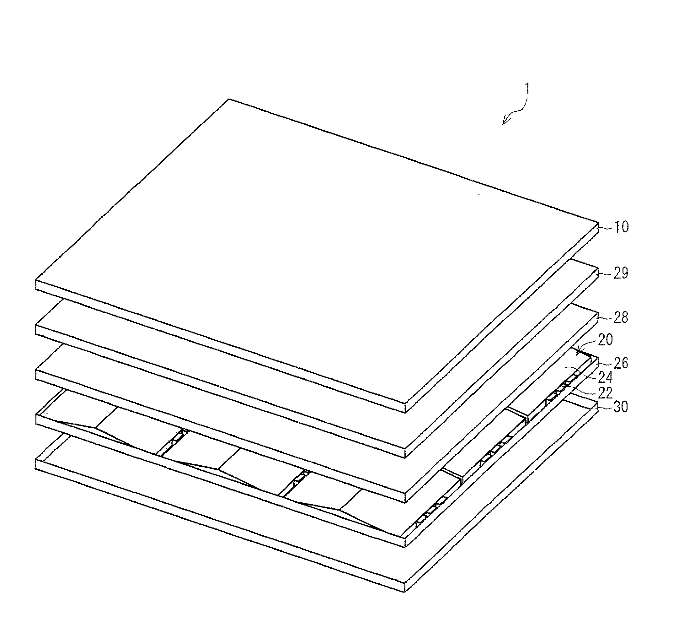
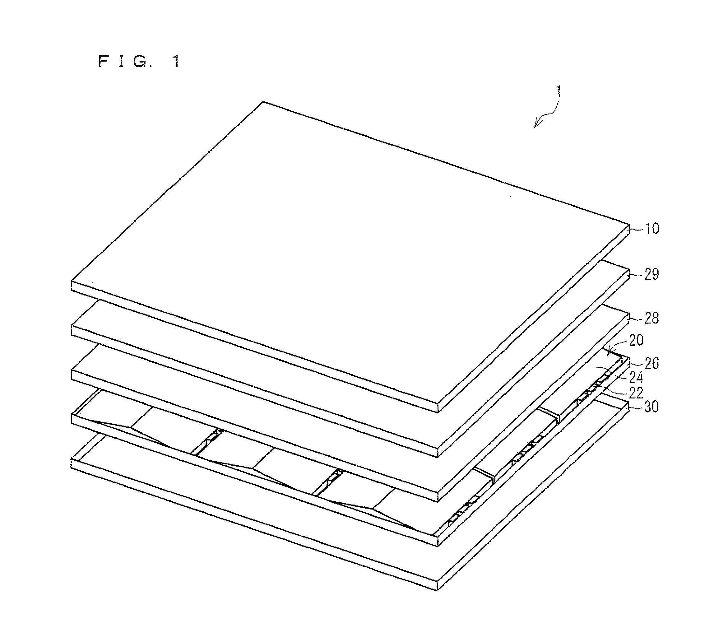
[0109]FIG. 1 is a perspective view illustrating a schematic structure of a liquid crystal display device 1 in the present embodiment.

[0110]The liquid crystal display device 1 in the present embodiment includes a liquid crystal display panel 10 and a backlight 20 as an illuminating device provided in the rear of the liquid crystal display panel 10.

[0111](Liquid Crystal Display Panel)

[0112]The liquid crystal display panel 10 is similar to a general liquid crystal display panel used for a conventional liquid crystal display device. For example, such a liquid crystal display panel includes (i) an active matrix substrate in which a plurality of TFTs (Thin Film Tr...

second embodiment

[0227]The following describes a second embodiment with reference to FIG. 7. Note that configurations which are not described in the present embodiment are the same as those in the first embodiment. Moreover, for convenience of explanation, members having the same functions as those shown in the drawings of the first embodiment are given the same reference numerals, and explanations of the members are omitted.

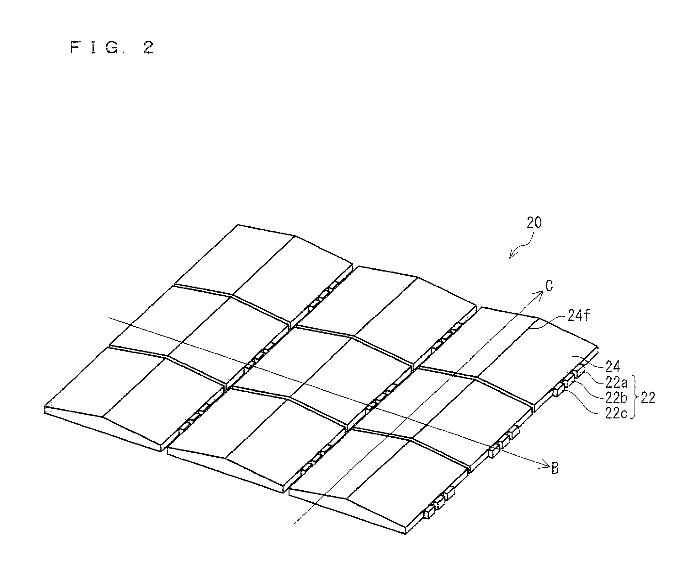
[0228]The backlight 20 in the present embodiment includes the light guide 24 having a shape different from that of the light guide 24 of the backlight 20 in the first embodiment.

[0229]That is, the light guide 24 in the first embodiment has the substantially mountain shape, and has the first light emitting face 24a and the second light emitting face 24b, which serve as planes.

[0230]On the other hand, the light guide 24 of the second embodiment has a shape, which is formed by a combination of prism shapes, thereby the light emitting face is not a single plane. As a whole, the shap...

third embodiment

[0240]The following describes a third embodiment of the present invention with reference to FIG. 8. Note that, in the present embodiment, configurations which are not described in the present embodiment are the same as those in the first and second embodiments. Moreover, for convenience of explanation, members having the same functions as those shown in the drawings of the first and second embodiments are given the same reference numerals, and explanations of the members are omitted.

[0241]The backlight 20 in the present embodiment includes the light guide 24 having a shape different from that of the light guide 24 of the backlight 20 in the second embodiment.

[0242]In the light guide 24 of the second embodiment, the transverse plane 24s forming the slant face of the mountain shape is parallel to the bottom surface 24c of the light guide 24. That is, the angle (see (i) the angle R1 shown in FIG. 4 and (ii) FIG. 7) formed by the transverse plane 24s and the bottom surface 24c is 0 degr...


PUM

PropertyMeasurementUnit
angleaaaaaaaaaa
angleaaaaaaaaaa
angleaaaaaaaaaa

Abstract

In a light guide unit (40) of the present invention, a light source (22) is provided on a first end section (24d) of a light guide (24). Further, a side reflective member (26b), which can reflect light in the light guide (24), is provided on a second end section (24e) opposite to the first end section (24d) which is provided with the light source (22). The light guide (24) is continuously increased in thickness (D2, D4, and D5) (i) from the first end section (24d) provided with the light source (22) toward a center of the light guide (24) and (ii) also from the second end section (24e) provided with the side face reflective member (26b) toward the center of the light guide (24).

Description

TECHNICAL FIELD[0001]The present invention relates to (i) a light guide unit which is used such as a backlight of a liquid crystal display device, (ii) an illuminating device, and (iii) a liquid crystal display device including the illuminating device.BACKGROUND ART[0002]In these years, liquid crystal display devices, which have rapidly become popular in replacement of cathode-ray tubes (CRT), are widely used in such as TVs, monitors, and mobile phones by making use of characteristics such as energy saving, thin body, and lightweight. Further, in some cases, an illumination device (i.e., a backlight) is provided in the rear of the liquid crystal display devices in the aim of spreading the use of the liquid crystal display device and improving display quality of the liquid crystal display device.[0003]In order to achieve the improvement in the display quality and the like, upgrading of the illuminating device is desired.[0004]The illuminating device can be classified mainly in a side...

Claims


Application Information

Patent Timeline
Patent Type & Authority Applications(United States)
IPC IPC(8): G02F1/1335G02F1/13357
CPCG02B6/0046G02F1/133615G02B6/0068G02B6/0048
Inventor KUBO, TOMOKIMASUDA, TAKESHI
Owner SHARP KK
Why Eureka
Try Eureka