Crushable polymeric rail extension, systems, and methods of making and using the same

a technology crushing polymer, which is applied in the field of crushing polymeric rail extension, systems, and making and using the same, can solve the problems of polymeric rail extension reducing performance, inadequacies in energy absorption, and low energy absorption

Active Publication Date: 2019-04-30
SABIC GLOBAL TECH BV
View PDF33 Cites 72 Cited by
  • Summary
  • Abstract
  • Description
  • Claims
  • Application Information

AI Technical Summary

Problems solved by technology

For example, a small space with a short rail extension can result in inadequate energy absorption.
In addition, a large space with a long rail extension can result in unstable buckling instead of progressive crushing, which can lead to low energy absorption.
Polymeric rail extensions can suffer from a reduction in performance due to high temperatures.
In addition, polymeric rail extensions can be damaged during a towing operation.
Furthermore, polymeric rail extensions are limited in the materials that are available for electrophoretic deposition (e.g., e-coating).
In addition, for high speed crashes, polymeric rail extensions may not absorb similar energy levels as a metal rail extension.
Rail extensions can also be limited by the method of manufacture.
In addition, tool ejection becomes a challenge when using injection molding.
Thus, it is difficult to provide structurally suitable reinforcements in specific areas within the rail extension when using injection molding techniques.
Vehicle rail extensions can slip against the bumper beam due to inadequate engagement resulting in an inefficient absorption of energy.
In addition, bumper beams with a “B-shaped” cross section can clash on impact, resulting in the upper portion and lower portion crushing improperly and reducing impact absorption.

Method used


Image

  • Crushable polymeric rail extension, systems, and methods of making and using the same
  • Crushable polymeric rail extension, systems, and methods of making and using the same
  • Crushable polymeric rail extension, systems, and methods of making and using the same

Examples


examples

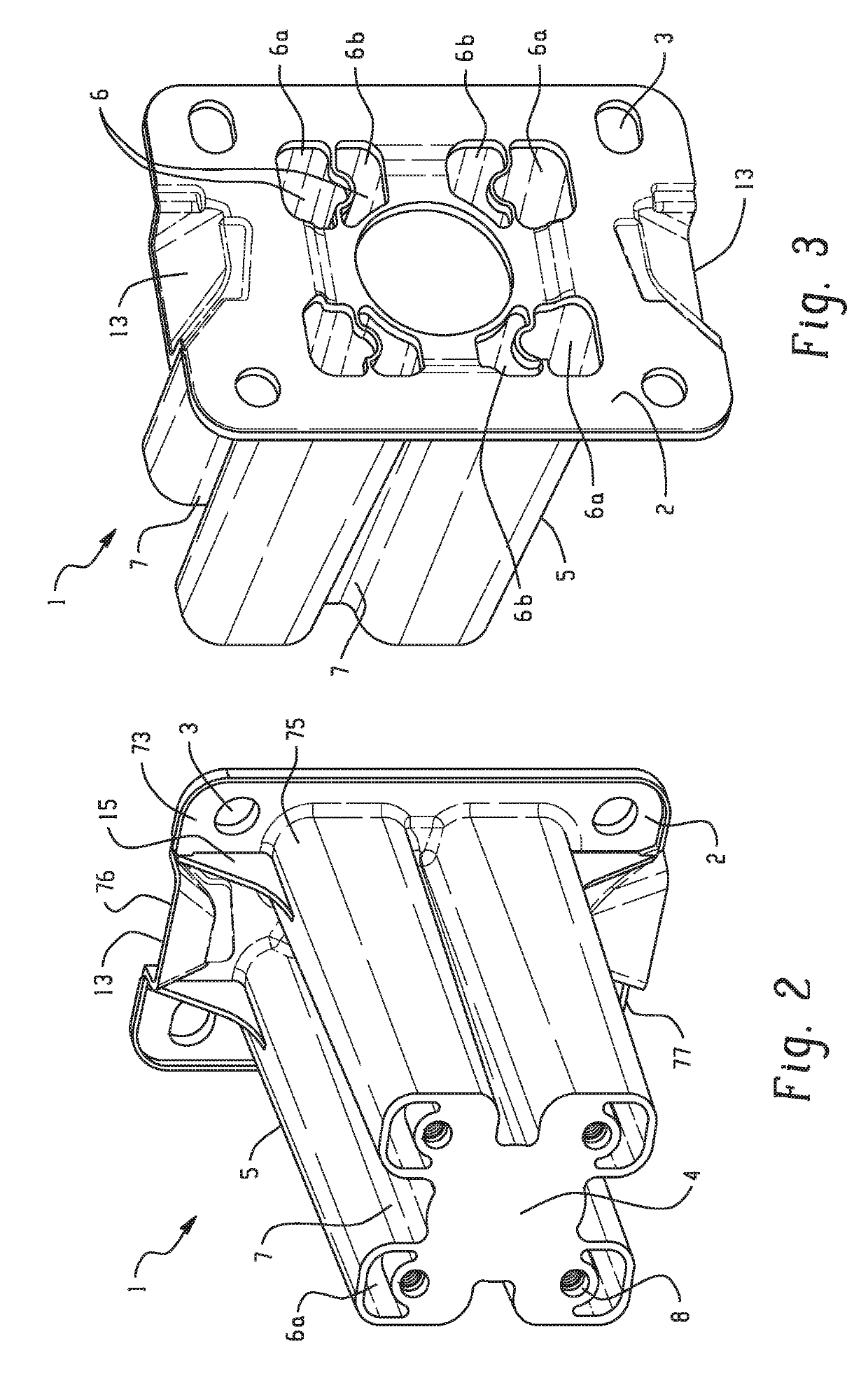
[0083]FIGS. 24-27 are graphic illustrations of displacement versus force for a simulated impact. The design of the simulations is for a 15 kilometer per hour (kmph) 40% offset RCAR impact of a pendulum against an assembly of a rail extension system. The intrusion is measured as the displacement of the pendulum and the force as that experienced by the rail extension on the side of impact. FIG. 24 illustrates the use of a polymeric rail extension directly joined to the bumper beam as shown in FIG. 2. As shown in FIG. 24, the polymeric rail extension (B) produces an intrusion similar to steel rail (A) extension while reducing part count. A blend of polyamide (PA) and polyphenylene ether polymer (PPE) is used (e.g., NORYL™ GTX™ resin, commercially available from SABIC's Innovative Plastics business). FIG. 25 illustrates the use of a polymeric rail extension including a plate having both an anti-clasher and an anti-climber as illustrated in FIG. 9. As shown in FIG. 25, the polymeric rail...


PUM

PropertyMeasurementUnit
chamfer angleaaaaaaaaaa
constant forceaaaaaaaaaa
forceaaaaaaaaaa

Abstract

A rail extension system (16), comprising: a vehicle rail (60); a bumper beam (20); a polymeric rail extension (1) comprising: a base (2) extending from one end of the rail extension having vehicle attachment configured to attach to the vehicle rail (60); a front member 4) configured for attachment to the bumper beam (20); a body (5) extending from the base (2) to the front member (4); an aperture (100) extending from the base (2) to the front member (4); a connection member (102) attached to the bumper beam (20) and extending through the aperture (100) to attach to the vehicle rail (60).

Description

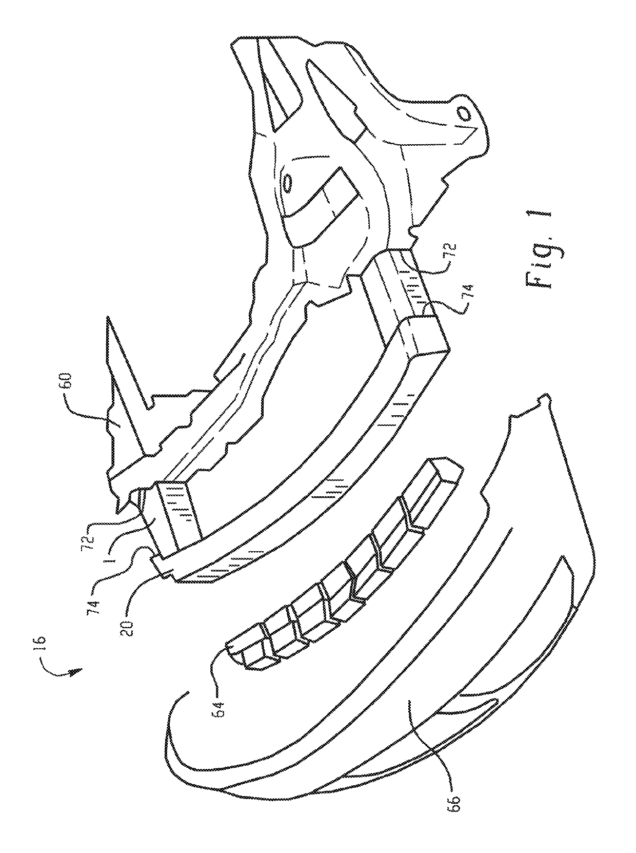
CROSS REFERENCE TO RELATED APPLICATIONS[0001]This application is a 371 of International Application No PCT / IB2015 / 055599, filed Jul 23, 2015, which claims the benefit of Provisional Application No. 62 / 102,821, filed Jan. 13, 2015, and Provisional Application No. 62 / 028,956, filed Jul 25, 2014, all of which are incorporated by reference in their entirety herein.BACKGROUND[0002]Bumper systems generally extend widthwise, or transversely, across the front and rear of a vehicle and are mounted to rails that extend in a lengthwise direction. Many bumper assemblies for an automotive vehicle include a bumper beam and an injection molded energy absorber secured to the bumper beam with a fascia covering the energy absorber. The system including one or more members that connect the bumper beam to the vehicle chassis / frame is called the rail extension system. Beneficial energy absorbing bumper systems achieve high efficiency by building load quickly to just under the load limit of the rails and...

Claims


Application Information

Patent Timeline
Patent Type & Authority Patents(United States)
IPC IPC(8): B60R19/34F16F7/12B29C45/00B60R19/26B29C45/16B29L31/30
CPCB60R19/34F16F7/12B60R2019/264B29C45/16B29L2031/3044B29C45/0005
Inventor MOHAPATRA, SUBHRANSU SEKHARGUMPINA, KRISHNA KISHOREBOBBA, SOMASEKHARPARAMESHWARA, ARUNACHALANARAYANASWAMY, VENKATESHA
Owner SABIC GLOBAL TECH BV
Why Eureka
Try Eureka