Packaging material for power storage device

a technology of power storage device and packaging material, which is applied in the direction of turning machines, metal-working apparatuses, synthetic resin layered products, etc., can solve the problems of high energy density lithium ion batteries, whitening is likely to occur in drawn portions, micro cracks are prone to occur in the sealing layer, etc., to improve sealing properties, reduce excess sealing portions, and good insulation properties

Active Publication Date: 2019-05-28
TOPPAN PRINTING CO LTD
View PDF18 Cites 1 Cited by
  • Summary
  • Abstract
  • Description
  • Claims
  • Application Information

AI Technical Summary

Benefits of technology

[0038]According to the first aspect of the present invention, there is provided a packaging material for a power storage device, which improves sealing properties, including degassing and heat sealing strength, in relation to the electrolytic solution, while reducing excess sealed portions and the occurrence of whitening due to forming.
[0039]According to the second aspect of the present invention, there is provided a packaging material for a power storage device, which has good insulation properties after forming and good sealing properties, including degassing and heat sealing strength, in relation to the electrolytic solution.

Problems solved by technology

Due to downsizing of cellular phones or limited spaces for installation, and other reasons, smaller power storage devices are sought.
Thus, lithium ion batteries with high energy density are attracting attention.
However, when the recess is deeper, micro cracks are prone to occur in the sealant layer due to strain caused during cold forming.
Specifically, whitening is likely to occur in the drawn portions, such as shaped surfaces and corners, of the sealant layer.
Whitening caused by cold forming reduces insulation properties and thus accelerates degradation of battery performance.

Method used


Image

  • Packaging material for power storage device
  • Packaging material for power storage device
  • Packaging material for power storage device

Examples


example 1-1

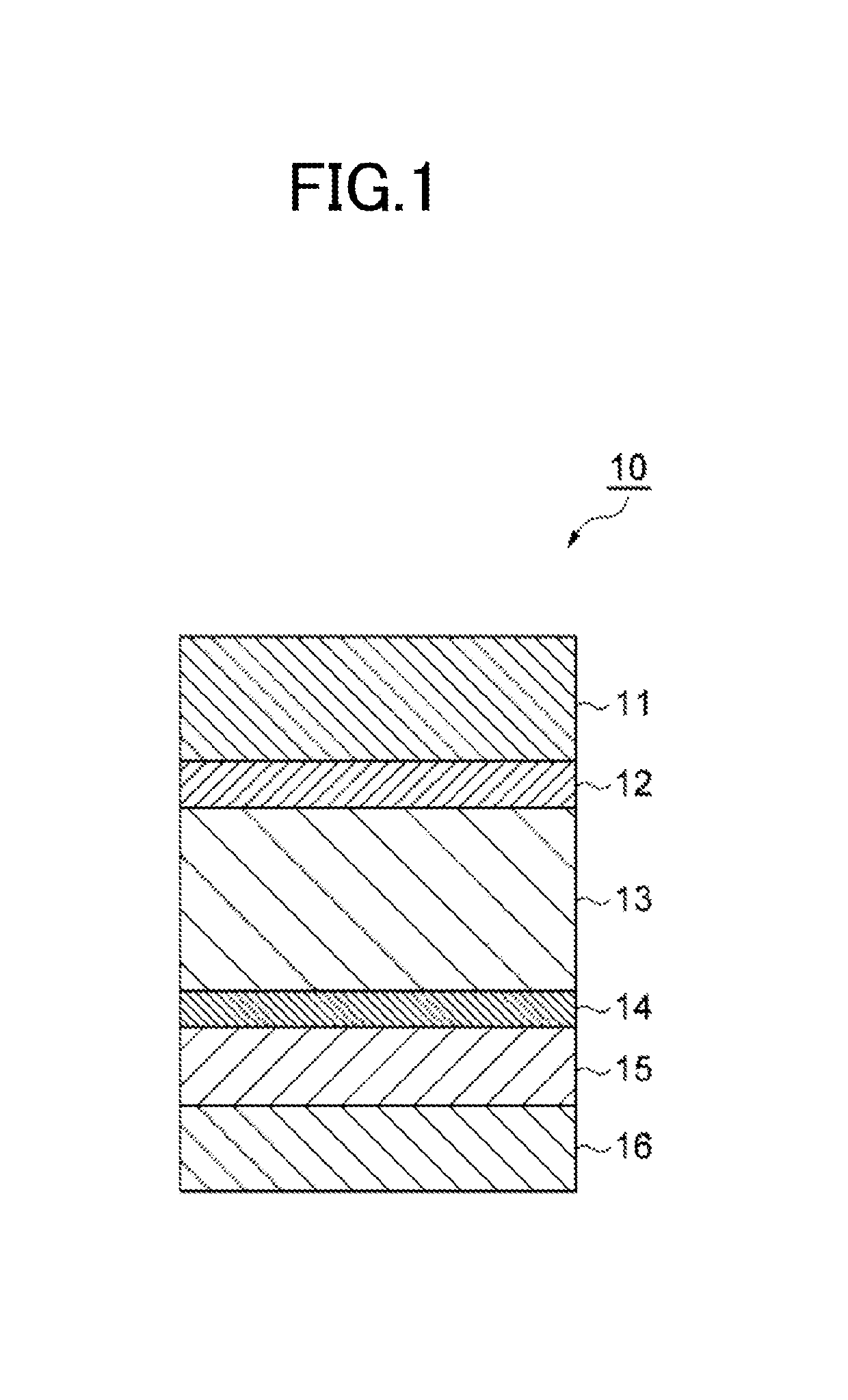
[0308]First, a first anti-corrosion treatment layer was provided to a metal foil layer according to the following procedure. That is, (CL-1-1) was applied to a surface of the metal foil layer by micro gravure coating with a dry coating amount of 70 mg / m2, followed by baking in a drying unit at 200° C. Subsequently, (CL-1-2) was applied to the resultant layer by micro gravure coating with a dry coating amount of 20 mg / m2, thereby forming a composite layer made of (CL-1-1) and (CL-1-2) as a first anti-corrosion treatment layer. This composite layer was allowed to express anti-corrosion performance by complexing the two materials, i.e. by complexing (CL-1-1) with (CL-1-2).

[0309]Subsequently, (CL-1-1) was applied to the other surface of the metal foil layer by micro gravure coating with a dry coating amount of 70 mg / m2, followed by baking in a drying unit at 200° C. Subsequently, (CL-1-3) was applied to the resultant layer by micro gravure coating with a dry coating amount of 20 mg / m2, ...

examples 1-2 to 1-7

[0312]Except that the resin compositions used for forming the sealant layer were changed to (SL-1-2) to (SL-1-7) (all 30 μm thickness), packaging materials of Examples 1-2 to 1-7 were produced similarly to Example 1-1.

example 1-8

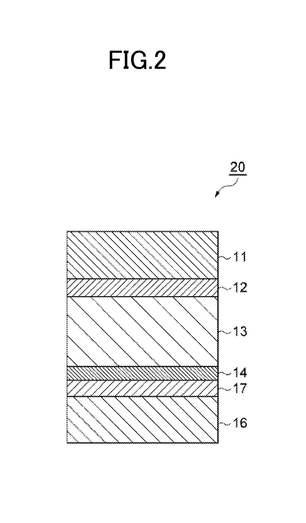
[0313]Similarly to Example 1-1, a laminate of base material layer / first adhesive layer / first anti-corrosion treatment layer / metal foil layer / second anti-corrosion treatment layer was prepared. Subsequently, an adhesive (second adhesive layer) was applied to the second anti-corrosion treatment layer by dry lamination with a dry coating amount of 4 to 5 g / m2, followed by drying for formation into a film, and then a sealant layer was bonded. The resin composition (SL-1-1) was formed into a film with a thickness of 45 μm and the adhesive-bonding surface thereof was corona-treated to obtain an unstretched cast film for use as the sealant layer. After that, the laminate was aged at 40° C. for 5 days, thereby producing a packaging material of Example 1-8 (laminate of base material layer / first adhesive layer / first anti-corrosion treatment layer / metal foil layer / second anti-corrosion treatment layer / second adhesive layer / sealant layer).


PUM


Abstract

A packaging material for a power storage device has a structure in which at least a base material layer, a first adhesive layer, a metal foil layer provided with an anti-corrosion treatment layer on one surface or both surfaces thereof, a second adhesive layer or an adhesive resin layer, and a sealant layer are laminated in this order. In the packaging material, the sealant layer includes a layer formed of a resin composition that contains 60 to 95 mass % propylene-ethylene random copolymer (A), and 5 to 40 mass % polyolefin elastomer (B) including 1-butene as a comonomer and having a melting point of 150° C. or less.

Description

CROSS-REFERENCE TO RELATED PATENT APPLICATIONS[0001]This application is a continuation application filed under 35 U.S.C. § 111(a) claiming the benefit under 35 U.S.C. §§ 120 and 365(c) of International Application No. PCT / JP2016 / 052521, filed on Jan. 28, 2016, which is based upon and claims the benefit of priority of Japanese Patent Application No. 2015-020328, filed on Feb. 4, 2015, and Japanese Patent Application No. 2015-090263, filed on Apr. 27, 2015, the entireties of which are hereby incorporated by reference.TECHNICAL FIELD[0002]The present invention relates to a packaging material for a power storage device.BACKGROUND[0003]Power storage devices that are well known include, for example, secondary batteries, such as lithium ion batteries, nickel hydrogen batteries, and lead batteries, and electrochemical capacitors, such as electric double layer capacitors. Due to downsizing of cellular phones or limited spaces for installation, and other reasons, smaller power storage devices...

Claims


Application Information

Patent Timeline
Patent Type & Authority Patents(United States)
IPC IPC(8): H01M2/02B32B15/08B32B7/12B23B7/12B32B15/20B32B27/32H01G11/78H01M10/052H01M50/105H01M50/119H01M50/121H01M50/129H01M50/133H01M50/145
CPCH01M2/02B32B7/12B32B15/08B32B15/20B32B27/32H01M2/0275H01M2/0277H01M2/0285H01M2/0287H01G11/78H01M10/052B32B27/08B32B15/088B32B15/09B32B27/36B32B27/34B32B15/18B32B2307/7246B32B2307/306B32B2307/714B32B2307/7265B32B2307/732B32B2553/00Y02E60/10H01M50/124H01M50/105H01M50/133H01M50/121H01M50/129H01M50/145H01M50/119B32B15/085C09J123/12
Inventor OGIHARA, YUSUZUTA, MASAYOSHI
Owner TOPPAN PRINTING CO LTD
Why Eureka
Try Eureka