Ink bottle

a technology of ink bottles and ink cartridges, applied in the field of ink bottles, can solve problems such as destroying the convenience of bottles

Active Publication Date: 2019-07-16
SEIKO EPSON CORP
View PDF41 Cites 23 Cited by
  • Summary
  • Abstract
  • Description
  • Claims
  • Application Information

AI Technical Summary

Problems solved by technology

This is one potential factor damaging the convenience of the bottle.

Method used


Image

  • Ink bottle
  • Ink bottle
  • Ink bottle

Examples


modification 1

[Modification 1]

[0095]According to the above embodiment, the second projection 124 is formed on the outer wall of the cylindrical portion 92 in the ink outlet forming portion 65, so that the level difference is formed between the cylindrical portion 92 and the second projection 124 as shown in FIG. 13. The configuration of the level difference is, however, not limited to the configuration of this embodiment. According to a modification, a fourth recess 135 may be formed in the outer wall of the cylindrical portion 92, so that a level difference may be formed between the cylindrical portion 92 and the fourth recess 135, as shown in FIG. 17. The coupling element 122 is provided at a position farther from the ink outlet 95 than the level difference (between the cylindrical portion 92 and the fourth recess 135) in the axial direction of the center axis CL of the ink outlet 95. The configuration of this Modification 1 provides similar advantageous effects to those of the above embodiment...

modification 2

[Modification 2]

[0096]According to Modification 2, as shown in FIG. 18, fixing claws 137 may be provided on the inner side of the ink outlet forming portion 65, such as to prevent dropout of the seal member 68. As shown in FIG. 19 that is a sectional view schematically illustrating an ink outlet forming portion 65 of Modification 2, a receiving region 138 is provided in the ink outlet forming portion 65 to place the seal member 68 therein. The fixing claws 137 are located at positions that initially do not overlap with the receiving region 138 in the plan view in the direction from the joint portion 91 toward the cylindrical portion 92. In this state, the seal member 68 is placed in the receiving region 138, and the fixing claws 137 are plastically deformed in the directions of arrows by caulking, bending or the like, such as to be protruded into the receiving region 138. The fixing claws 137 thus prevent dropout of the seal member 68 from the receiving region 138 toward the joint p...


PUM


Abstract

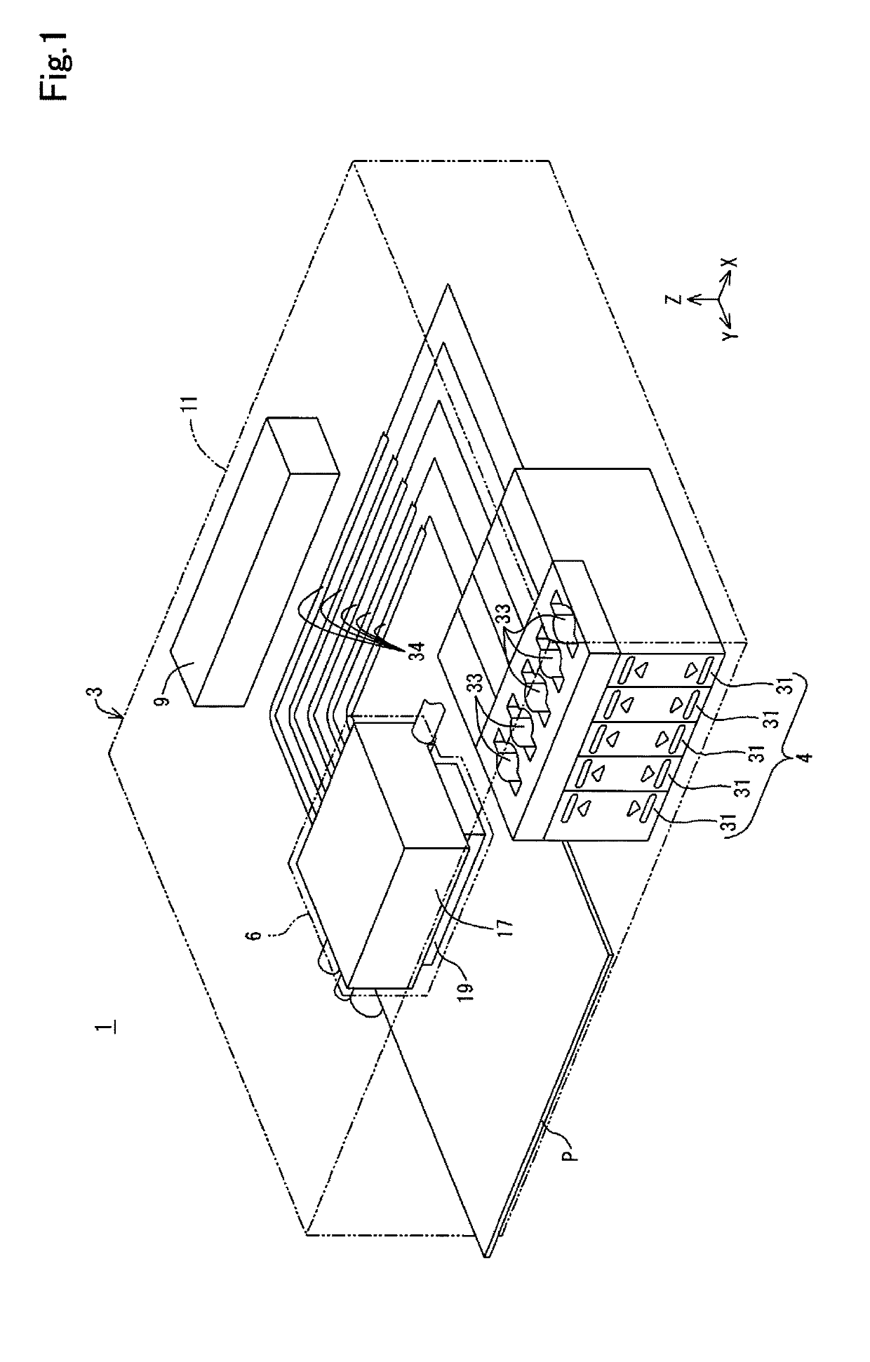
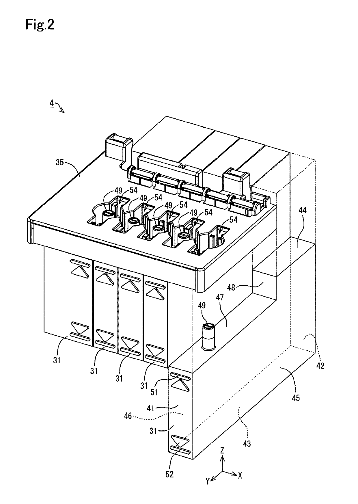
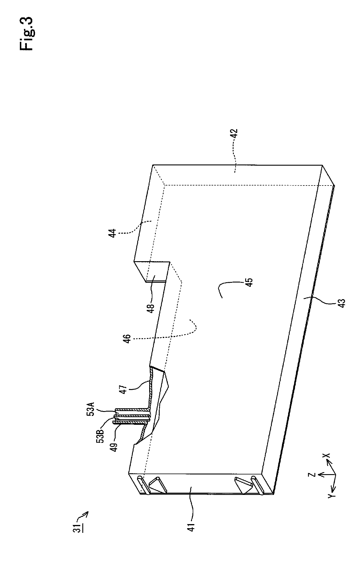
An ink bottle comprises a container main body configured to contain ink that is to be supplied to an ink tank, an ink outlet forming portion provided on an end of the container main body and configured to include an ink outlet that causes the ink to be flowed out from the container main body, and a valve provided in the ink outlet forming portion and configured to seal the ink outlet in an openable and closable manner. The ink outlet is formed in an end face of the ink outlet forming portion. The end face is arranged to face an opposite side of the ink outlet forming portion that is opposite to a container main body side thereof. A first recess is formed in an outer side portion of the ink outlet on the end face to be recessed toward the container main body side.

Description

CROSS-REFERENCE TO RELATED APPLICATION[0001]The present application claims priority from Japanese patent applications No. 2016-203332 filed on Oct. 17, 2016, No. 2016-116155 filed on Jun. 10, 2016 and No. 2016-208864 filed on Oct. 25, 2016, the entirety of the content of which are hereby incorporated by reference into this application.BACKGROUNDField[0002]The disclosure relates to an ink bottle.Related Art[0003]A conventionally known inkjet printer as one example of an ink ejection apparatus is configured to eject ink from a record head toward a recording medium such as recording paper, such as to perform printing on the recording medium with the ink. The inkjet printer may be configured to allow the user to supply ink to a tank provided to store ink that is to be supplied to the record head. There is also a bottle (ink bottle) known to be suitable for injection of ink into the tank (as described in, for example, JP 2014-88207A).[0004]When the bottle described in JP 2014-88207A is i...

Claims


Application Information

Patent Timeline
Patent Type & Authority Patents(United States)
IPC IPC(8): B41J2/175
CPCB41J2/17553B41J2/1752B41J2/17503B41J2/17513B41J2/17523B41J2/17596B41J2/17509B41J2/17536B41J2/1754B41J29/02B41J29/13B41J2002/17573B41J2/17506B65D2583/005B41J2/175B41J2/1753B41J2/17533
Inventor MIZUTANI, TADAHIROTOBA, KOICHITANAKA, RYOICHIISHIZAWA, TAKUAKAHANE, MANABUWATANABE, TADASHIFUKASAWA, NORIYUKI
Owner SEIKO EPSON CORP
Why Eureka
Try Eureka