Liquid surface sensing device
a sensing device and liquid surface technology, applied in the direction of measurement devices, level indicators, instruments, etc., can solve the problems and achieve the effect of adversely affecting the sensing results and the deterioration of the sensing uni
- Summary
- Abstract
- Description
- Claims
- Application Information
AI Technical Summary
Benefits of technology
Problems solved by technology
Method used
Image
Examples
first embodiment
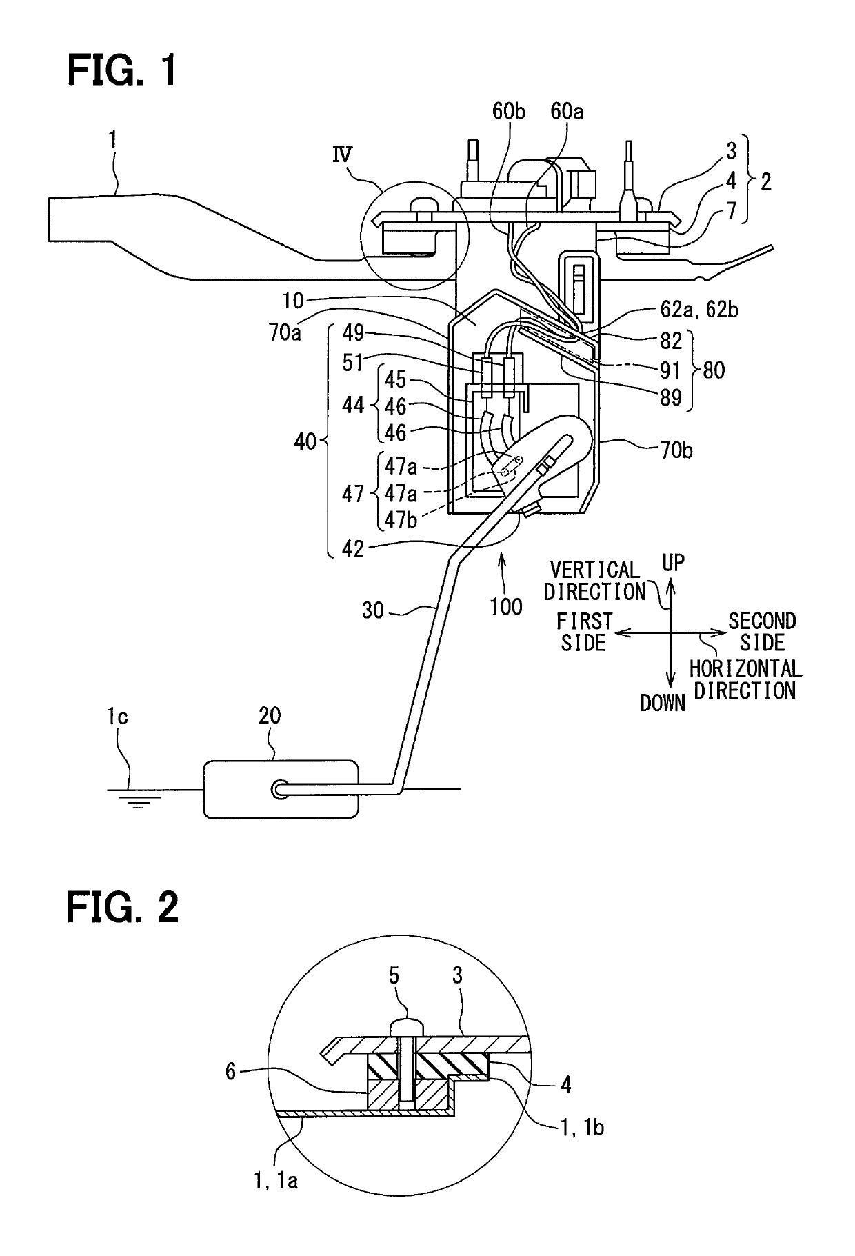
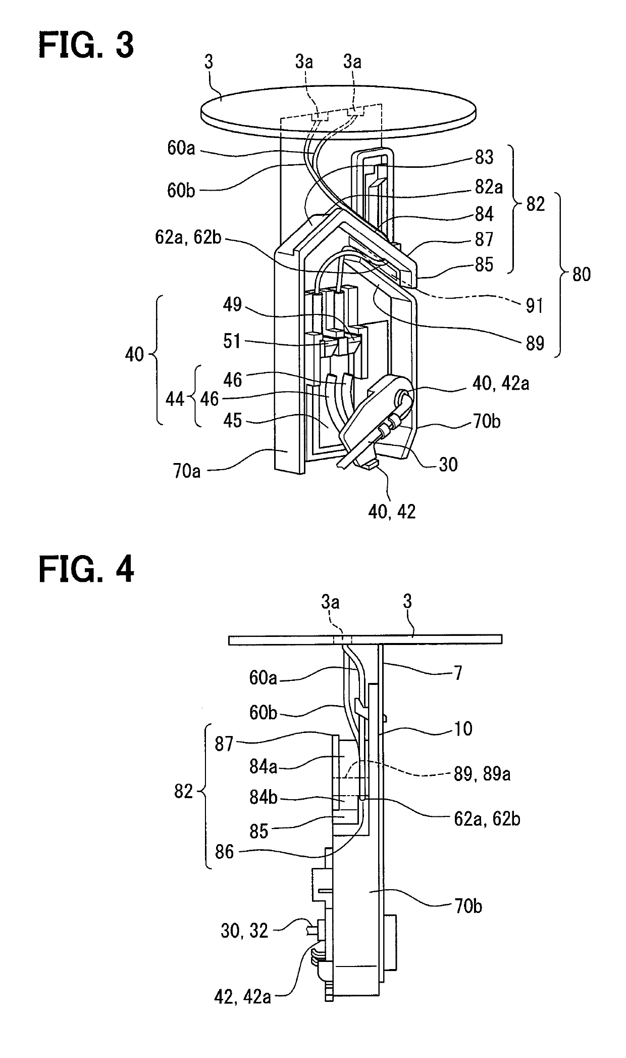
[0018]As illustrated in FIGS. 1 and 2, a liquid surface sensing device 100 of the first embodiment is installed inside a fuel tank 1, which is a container storing fuel, which is a liquid, and assembled to an assembling unit 2. Although not illustrated, the fuel tank 1 is mounted on a vehicle.
[0019]In the present embodiment, as illustrated in FIG. 1, the vertical direction coincides with the direction of gravity applied to the vehicle and the fuel tank 1. The horizontal direction coincides with the direction along a liquid surface 1c when the fuel is stored in the fuel tank 1, i.e., a direction perpendicular to the vertically upward and downward directions.
[0020]The assembling unit 2 includes a flange 3, a gasket 4, and a holder plate 7. The flange 3 is a disc-like lid made of plated iron or the like and closes an opening 1b formed in a ceiling part 1a of the fuel tank 1 from vertically above. The flange 3 may be made of a synthetic resin such as polyacetal instead of metal.
[0021]The...
second embodiment
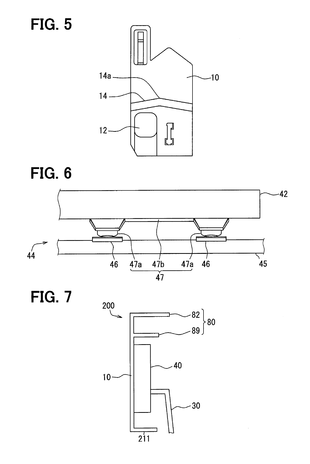
[0052]As illustrated in FIG. 7, the second embodiment of the present disclosure is a modification of the first embodiment. The second embodiment will now be described, mainly in respect of the points different from the first embodiment.
[0053]The holder wall 10 of a liquid surface sensing device 200 in the second embodiment has a laterally protruding wall 211 protruding in the horizontal direction vertically below the sensing unit 40. More particularly, the laterally protruding wall 211 is connected to the lower ends of the holder wall 10 and side walls 70a and 70b, and covers the sensing unit 40 from vertically below.
[0054]The shape of the guide 80 and the routing of the lead wires 60a and 60b are the same in the second embodiment, so that advantageous effects similar to those of the first embodiment can be achieved.
[0055]According to the second embodiment, the holder wall 10 includes the laterally protruding wall 211 protruding in the horizontal direction vertically below the sensi...
PUM
 Abstract
Description
Claims
Application Information
 - R&D
- Intellectual Property
- Life Sciences
- Materials
- Tech Scout
- Unparalleled Data Quality
- Higher Quality Content
- 60% Fewer Hallucinations
Browse by: Latest US Patents, China's latest patents, Technical Efficacy Thesaurus, Application Domain, Technology Topic, Popular Technical Reports.
© 2025 PatSnap. All rights reserved.Legal|Privacy policy|Modern Slavery Act Transparency Statement|Sitemap|About US| Contact US: help@patsnap.com


