
Liquid surface sensing device

a sensing device and liquid surface technology, applied in the direction of measurement devices, level indicators, instruments, etc., can solve the problems and achieve the effect of adversely affecting the sensing results and the deterioration of the sensing uni

Active Publication Date: 2016-11-10
DENSO CORP
View PDF10 Cites 2 Cited by
  • Summary
  • Abstract
  • Description
  • Claims
  • Application Information

AI Technical Summary

Benefits of technology

The patent aims to provide a liquid surface sensing device that prevents the liquid composition from adhering or bonding to the metals of the sensing unit, which may cause deterioration of the sensing unit or adversely affect the sensing results. The device includes a guide that bends the lead wire and forms the valley portion to direct the lead wire diagonally upward, which causes the liquid composition to stay in the valley portion and to hard travel from the valley portion towards the sensing unit.

Problems solved by technology

It prevents the liquid composition from adhering or bonding to metals used in the sensing unit, which may cause deterioration of the sensing unit or adversely affect the sensing results.

Method used


Image

  • Liquid surface sensing device
  • Liquid surface sensing device
  • Liquid surface sensing device

Examples


first embodiment

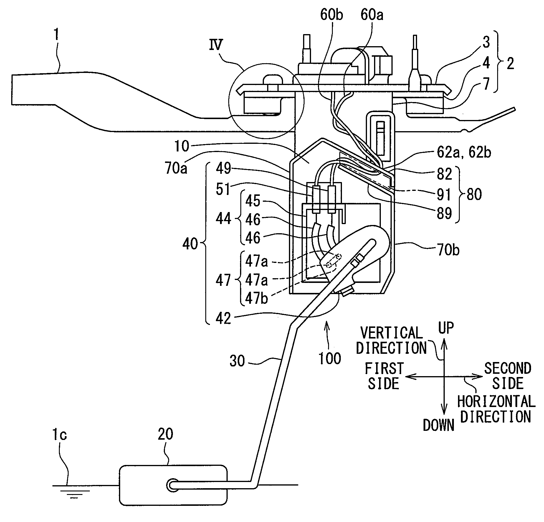
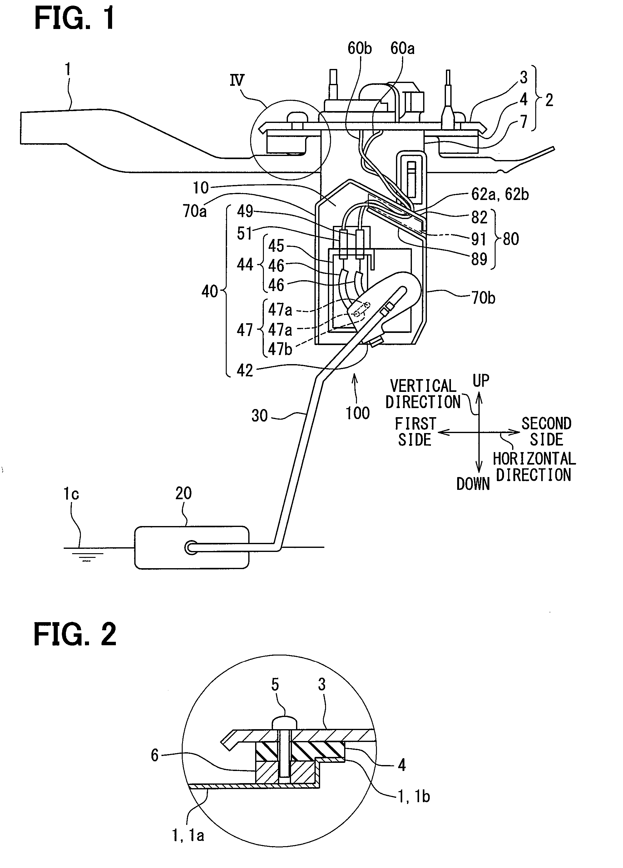
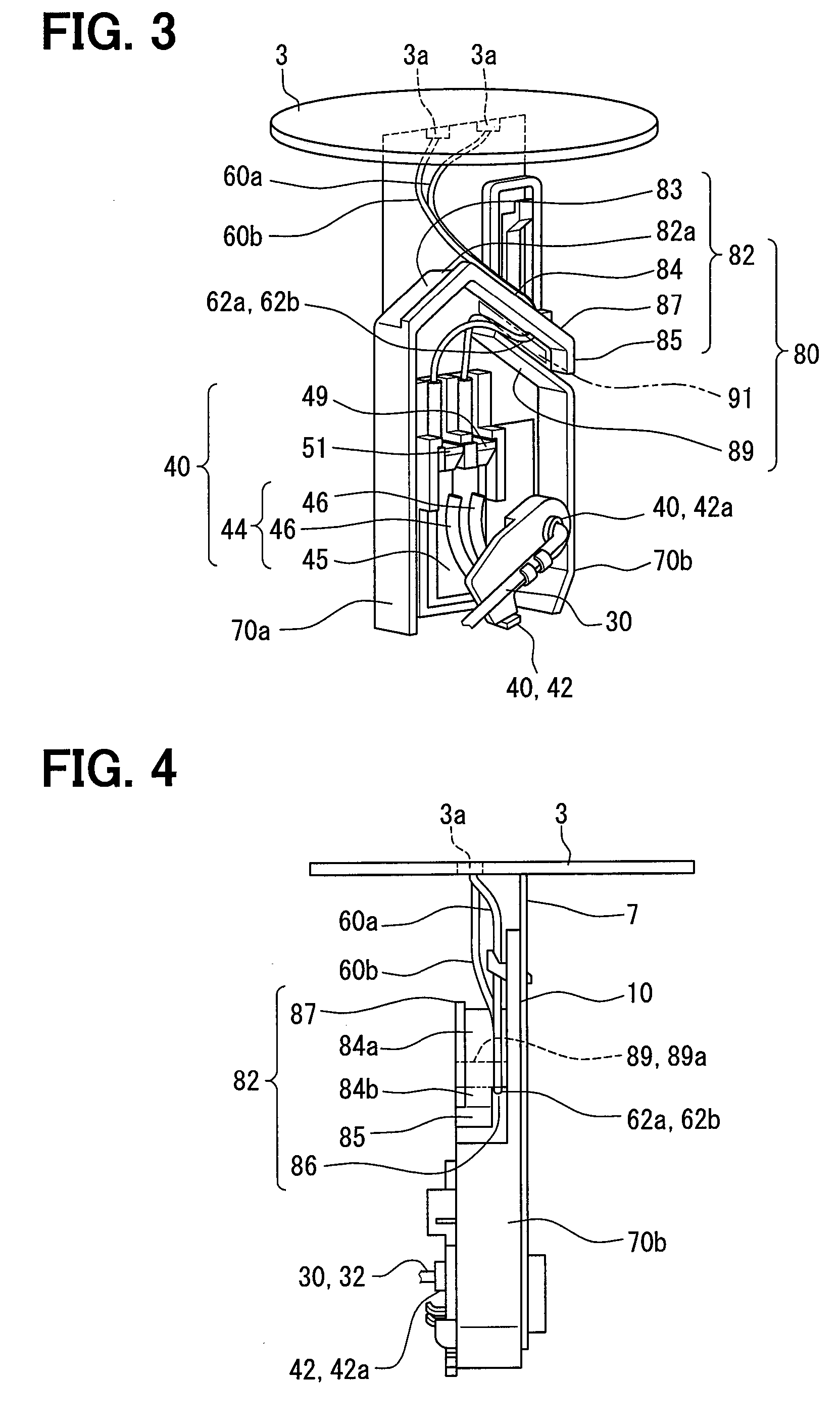
[0018]As illustrated in FIGS. 1 and 2, a liquid surface sensing device 100 of the first embodiment is installed inside a fuel tank 1, which is a container storing fuel, which is a liquid, and assembled to an assembling unit 2. Although not illustrated, the fuel tank 1 is mounted on a vehicle.

[0019]In the present embodiment, as illustrated in FIG. 1, the vertical direction coincides with the direction of gravity applied to the vehicle and the fuel tank 1. The horizontal direction coincides with the direction along a liquid surface 1c when the fuel is stored in the fuel tank 1, i.e., a direction perpendicular to the vertically upward and downward directions.

[0020]The assembling unit 2 includes a flange 3, a gasket 4, and a holder plate 7. The flange 3 is a disc-like lid made of plated iron or the like and closes an opening 1b formed in a ceiling part 1a of the fuel tank 1 from vertically above. The flange 3 may be made of a synthetic resin such as polyacetal instead of metal.

[0021]The...

second embodiment

[0052]As illustrated in FIG. 7, the second embodiment of the present disclosure is a modification of the first embodiment. The second embodiment will now be described, mainly in respect of the points different from the first embodiment.

[0053]The holder wall 10 of a liquid surface sensing device 200 in the second embodiment has a laterally protruding wall 211 protruding in the horizontal direction vertically below the sensing unit 40. More particularly, the laterally protruding wall 211 is connected to the lower ends of the holder wall 10 and side walls 70a and 70b, and covers the sensing unit 40 from vertically below.

[0054]The shape of the guide 80 and the routing of the lead wires 60a and 60b are the same in the second embodiment, so that advantageous effects similar to those of the first embodiment can be achieved.

[0055]According to the second embodiment, the holder wall 10 includes the laterally protruding wall 211 protruding in the horizontal direction vertically below the sensi...


PUM


Abstract

A liquid surface sensing device is installed in a fuel tank having an opening in a ceiling part. The opening is closed by a flange with a gasket constituted by an elastomer providing a seal between the flange and a peripheral edge of the opening. The liquid surface sensing device being assembled to the flange includes a sensing unit disposed vertically below the flange and sensing a liquid surface of a liquid, a lead wire connecting the sensing unit to an external device via the flange, and a guide bending the lead wire extending diagonally downward from the flange to form a valley portion to direct the lead wire diagonally upward.

Description

CROSS REFERENCE TO RELATED APPLICATION[0001]This application is based on Japanese Patent Application No. 2014-9872 filed on Jan. 22, 2014, the disclosure of which is incorporated herein by reference.TECHNICAL FIELD[0002]The present disclosure relates to a liquid surface sensing device that senses the liquid surface of a liquid.BACKGROUND ART[0003]Liquid surface sensing devices that sense the liquid surface of a liquid have hitherto been known. In a device described in Patent Literature 1, an opening is formed in the ceiling of a fuel tank, with a lid closing the opening. A lead wire connects a liquid surface sensor having a sensing unit such as a hole IC or the like with an external device.[0004]To improve the sealing properties between the fuel tank and the lid, it has been common in recent years to provide a rubber gasket between the fuel tank and the lid. However, such a gasket may suffer bleeding which is an exuding phenomenon of a liquid composition contained in the gasket, and...

Claims


Application Information

Patent Timeline
IPC IPC(8): G01F23/36
CPCG01F23/363
Inventor MIYAGAWA, ISAOHASHIMOTO, HIROSHI
Owner DENSO CORP
Learn More