
vehicle

A vehicle and wheel technology, applied to vehicle components, hybrid vehicles, vehicle subunit functions, etc., to protect the fixed part of the wire, improve safety performance, and suppress the effect of wire grounding

Active Publication Date: 2019-05-07
HONDA MOTOR CO LTD
View PDF9 Cites 0 Cited by
  • Summary
  • Abstract
  • Description
  • Claims
  • Application Information

AI Technical Summary

Problems solved by technology

[0009] However, in the electric vehicle described in Patent Document 1, when a collision from the front side (hereinafter referred to as a front collision) occurs that greatly affects the drive unit 101

Method used


Image

  • vehicle
  • vehicle
  • vehicle

Examples


Embodiment Construction

[0044] Hereinafter, the vehicle of the present embodiment will be described by taking a hybrid vehicle as an example.

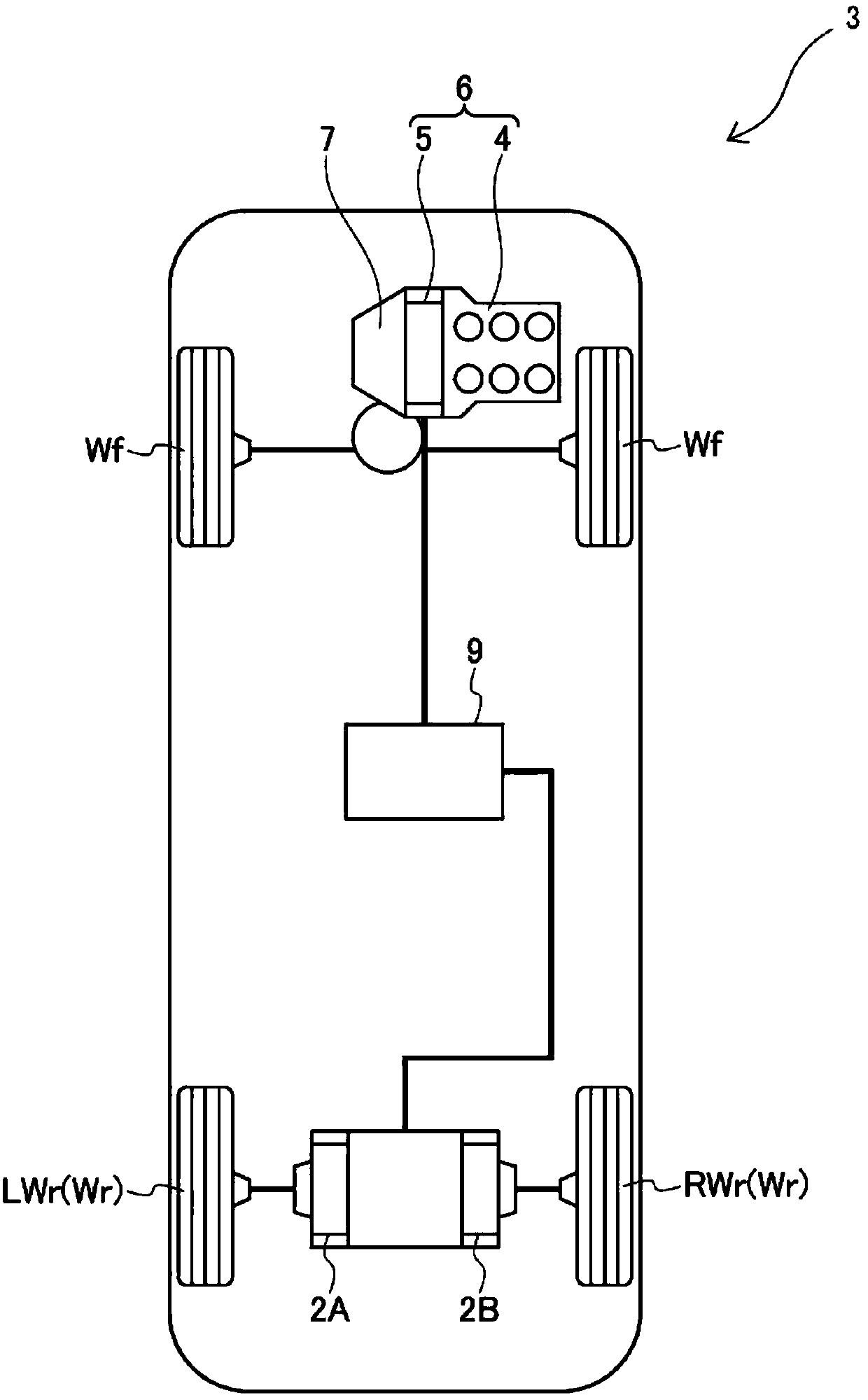
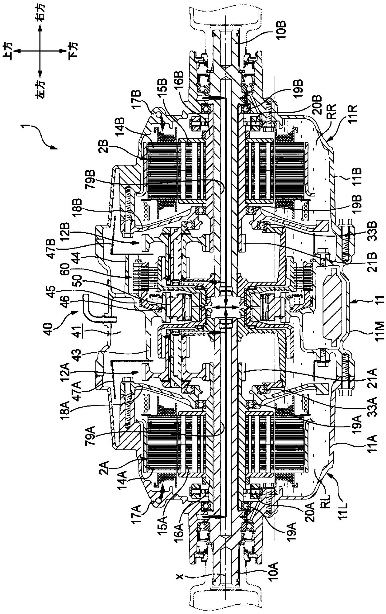
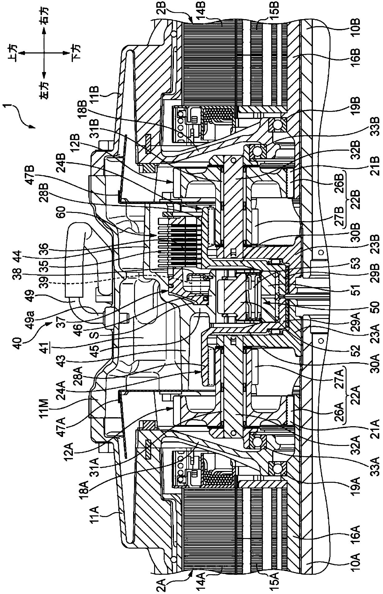
[0045] figure 1 The illustrated vehicle 3 is a hybrid vehicle having a driving device 6 (hereinafter referred to as a front-wheel drive device) in which an internal combustion engine 4 and an electric motor 5 are connected in series at the front of the vehicle. The transmission 7 transmits the transmission to the front wheels Wf. On the other hand, the driving device 1 (hereinafter referred to as the rear-wheel driving device 1 ) provided at a position lower than the floor (not shown) in the rear of the vehicle separately from the front-wheel driving device 6 device.) is transmitted to the rear wheels Wr (RWr, LWr). The rear wheel drive device 1 includes a first electric motor 2A and a second electric motor 2B, the power of the first electric motor 2A is transmitted to the left rear wheel LWr, and the power of the second electric motor 2B is transmitted to ...


PUM


Abstract

The present invention provides a vehicle (3), wherein a first motor and a second motor (2A, 2B) are supported on a subframe of the vehicle (3) via a bracket (81A, 81B) and a support portion (82A, 82B) (13), wherein, the rear fixing parts (92A, 92B) and the front fixing parts ( 91A, 91B), the rear fixing portion (92A, 92B) located near the rear side is formed at a vertically higher position than the front fixing portion (91A, 91B) located near the front side. On the first motor and the second motor (2A, 2B), in a side view, the imaginary straight line (y) passing through the center of the front fixing part (91A, 91B) and the center of the rear fixing part (92A, 92B) A first connector and a second connector (101A, 101B) for fixing a conductive cable (103A, 103B) for supplying electric power are formed at a lower position.

Description

technical field [0001] The present invention relates to a vehicle including an electric motor that drives wheels of the vehicle. Background technique [0002] Electric vehicles such as electric vehicles and hybrid vehicles are provided with a motor for driving the vehicle, and the motor is usually arranged offset to one side with respect to a passenger space (cabin) located at the center in the front-rear direction of the electric vehicle. [0003] For example, in the electric vehicle described in Patent Document 1, as Figure 6A As shown, a drive unit 101 including an electric motor is disposed on the front side of a dash panel 100 that partitions a passenger space. The drive unit 101 is supported by each mounting device at its upper ends at both left and right ends and its rear lower end, and the rear lower end is rotatably supported about a shaft extending in the vehicle width direction. Therefore, at the time of a collision from the front side, the lower end of the rear...

Claims


Application Information

Patent Timeline
Patent Type & Authority Patents(China)
IPC IPC(8): B60K1/00
CPCB60K1/00B60K1/02B60K17/16B60K2001/001B60K6/46B60K6/52B60K7/0007B60K17/046B60K2007/0046B60K2007/0092B60Y2400/427B60L3/00Y02T10/62Y02T10/64B60K6/00B60Y2200/92B60Y2200/91
Inventor 西田诚人
Owner HONDA MOTOR CO LTD
Learn More