
Flanged tone chamber window for woodwind mouthpieces

a technology of woodwind instruments and mouthpieces, which is applied in the direction of wind instruments, instruments, musical instruments, etc., can solve the problems and achieve the effect of reducing the “q” of the oscillating system and modifying the shape of the tone chamber

Active Publication Date: 2019-08-27
ROVNER PROD INC
View PDF86 Cites 0 Cited by
  • Summary
  • Abstract
  • Description
  • Claims
  • Application Information

AI Technical Summary

Benefits of technology

[0006]The present invention is directed to mouthpieces for woodwind instruments with modifications that soften the abrupt or perpendicular shock fronts at the aperture defined between the reed and each one of the tip rail and side rail top surfaces. In addition, the shape of the tone chamber is modified. During operation of the mouthpiece, the reed functions as a reed valve, opening and closing the gap or aperture in oscillatory cooperation with the air column of the instrument. During any portion of the oscillatory cycle, the gap is either fully open, partially open or barely open. Configurations of the aperture and tone chamber that generate shock fronts degrade the flow of the airstream, which is a dampening factor that reduces the “Q” of the oscillating system. The “Q” is a quality factor that provides a measure of underdamping in the oscillating system of the mouthpiece and reed. In addition, the quality factor can express the bandwidth of frequencies passing through the oscillating system relative to the central frequency of the oscillating system.
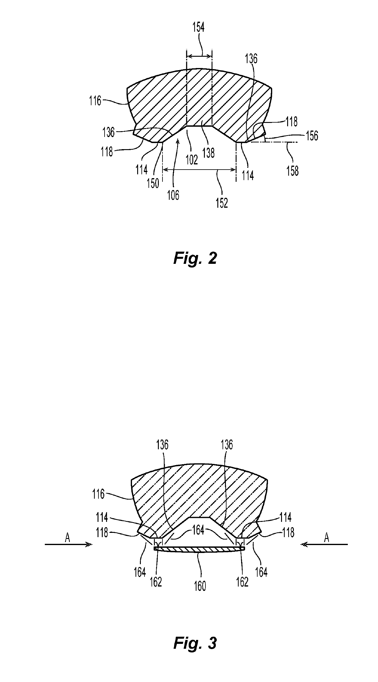
[0008]Each side rail includes a side rail top surface and an interior surface, i.e., interior to the tone chamber, running from the top surface of the side rail to the bottom surface of the tone chamber. Exemplary embodiments modify the side rail top surface, the interior surfaces of the tone chamber and the bottom surface of the tone chamber to reduce the abruptness of the aperture or opening to the gap between the reed and the mouthpiece, reducing the impedance mismatch and lowering the intensity of the shock fronts. In general, the surfaces are modified to create a tapered or funnel shaped transitions, yielding a venturi that softens the shock intensity and enabling a higher mass flow of airstream through the gap or aperture. The shape of the tone chamber also has the tapered or funnel shape to reduce abrupt changes in impedance within the tone chamber and to utilize the benefit of a “shaped charge” effect that improves the focus of the pressure zones in the chamber against the reed.
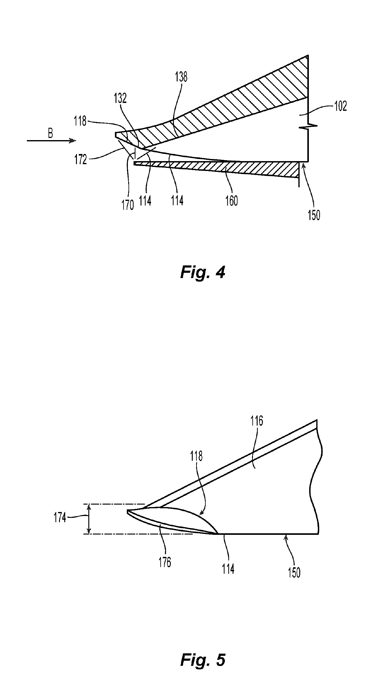
[0009]Exemplary embodiments improve the airflow through the aperture defined between the bottom of the reed and each top rail by effecting a geometry of the external surface of the mouthpiece at the inlet to the aperture, i.e., at extending in from the outer surface of the mouthpiece. This effectively forms a funnel, or venturi inlet, that reduces the intensity of the shock front that forms at the inlet of a more abrupt geometry. This configuration provides an improvement in overall performance results from such a configuration. In one embodiment, the width of the funnel shapes on the inlet surfaces of the mouthpiece is a function of the gap width of the mouthpiece and is selected to effect a 29.8° included angle to the perpendicular place of the gap at the contact points of the reed and mouthpiece. This angle is derived from the standard divergent angle of rocket exhaust flares, which has been determined to be the angle which transforms the impedance between the rocket nozzle and the outside environment.
[0010]With the reed placed over the window and in contact with the side rails and tip rail of the mouthpiece, the station of the tip region where an aperture is formed is the region up to about the first 25 mm, (1 inch) of the tip of the mouthpiece. The direction of airflow during the negative-pressure portion of the oscillation of the reed is from the outer surface of the mouthpiece across the tip rails and the side rails and into the window of the tone chamber. Therefore, the interface between the outer surface of the mouthpiece and the top surfaces of the side rails affects the functioning of the aperture. An abrupt geometry is not conducive to enabling an efficient flow of air through the aperture as this abrupt geometry produces shock fronts perpendicular to the direction of flow of the column of air. Therefore, exemplary embodiments provide a flange extending from the window and preferably angled away from the side rail top surfaces and tip rail. In addition, the interior surfaces of the tone chamber are also sloped or tapered. This forms a beveled or slope surface defining a funnel or venturi inlet that more effectively induces airflow through the aperture during the negative-pressure portion of the oscillatory cycle. The shock fronts extending from the bottom of the reed migrate along these tapered or sloped surfaces, producing shock fronts that are not perpendicular to the direction of flow of the air column. This reduces damping of the system, resulting in an improvement in performance.

Problems solved by technology

Configurations of the aperture and tone chamber that generate shock fronts degrade the flow of the airstream, which is a dampening factor that reduces the “Q” of the oscillating system.

Method used


Image

  • Flanged tone chamber window for woodwind mouthpieces
  • Flanged tone chamber window for woodwind mouthpieces
  • Flanged tone chamber window for woodwind mouthpieces

Examples


Embodiment Construction

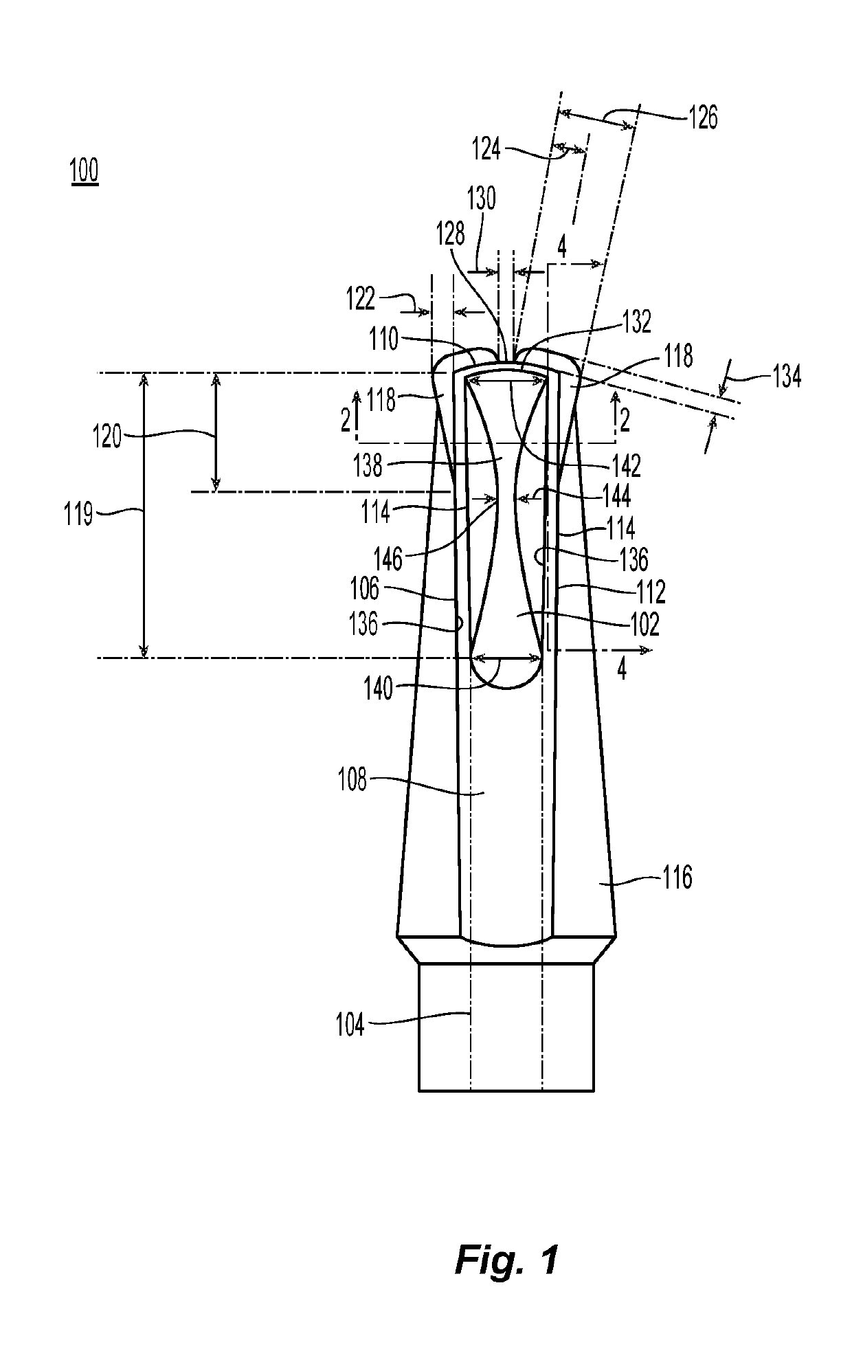
[0022]Referring initially to FIG. 1, an exemplary embodiment of a woodwind mouthpiece 100 in accordance with the present invention is illustrated. The view of the mouthpiece is from the side of the mouthpiece configured to engage a reed. This side of the mouthpiece is called the bottom of the mouthpiece as this side is positioned pointing downward or on the bottom when the mouthpiece is attached to a saxophone or clarinet. The woodwind mouthpiece includes a tone chamber 102 in communication with a central bore 104 running through the mouthpiece.

[0023]The mouthpiece also includes a window 106 exposing the tone chamber 102 disposed within the mouthpiece. The mouthpiece includes a table 108 at a first end of the window and a tip rail 110 at a second end of the window opposite the first end. A pair of side rails 112 extend from the table and run along opposite sides of the window from the table to the tip rail. Each side rail includes a side rail top surface 114. The window 106 is a gen...


PUM


Abstract

A woodwind mouthpiece has a tone chamber in communication with a central bore running through the mouthpiece and a window exposing the tone chamber. A table is located at a first end of the window, and a tip rail is located at a second end of the window opposite the first end. A pair of side rails run along opposite sides of the window from the table to the tip rail. Each side rail includes a side rail top surface. A pair of flanges are provided in the mouthpiece such that each flange extending out from one of the side rail top surfaces in a direction opposite the window. This arrangement reduces the intensity of the shock fronts at the aperture into the tone chamber.

Description

FIELD OF THE INVENTION[0001]The present invention relates to woodwind instruments and in particular to mouthpieces for woodwind instruments.BACKGROUND OF THE INVENTION[0002]Woodwind musical instruments, e.g., saxophones and clarinets, and other devices such as bird calls, utilize the vibration of a reed in response to a flow of air to generate a tone. These reeds include natural cane reeds and synthetic reeds. Tone generation in general depends on proper reed vibration. The reed is typically placed in contact with a mouthpiece to cover an opening or window. The reed is held in place by an adjustable clamp or ligature that surrounds the mouthpiece and the reed. Variations in the mouthpiece and ligature affect the vibration of the reed and, therefore, the performance or tone of the device or instrument.[0003]The essential function of the mouthpiece of a woodwind instrument is to provide support for the reed over an aperture that allows the reed to vibrate and to direct the energy from...

Claims


Application Information

Patent Timeline
Patent Type & Authority Patents(United States)
IPC IPC(8): G10D9/02G10D7/06
CPCG10D9/02G10D7/06
Inventor ROVNER, PHILIP LEE
Owner ROVNER PROD INC
Learn More