Reconfigurable ultrasonically sculpted optical beam paths

a technology of ultrasonically sculpted optical beams and beam paths, which is applied in the field of reconfigurable ultrasonically sculpted optical beam paths, can solve the problems of reducing the depth of penetration of light, reducing the spatial resolution, and requiring millions of unique measurements for accurate focusing, and achieves the effect of inducing a temporary refractive index profil

Active Publication Date: 2020-12-08
CARNEGIE MELLON UNIV
View PDF11 Cites 0 Cited by
  • Summary
  • Abstract
  • Description
  • Claims
  • Application Information

AI Technical Summary

Benefits of technology

[0007]A novel approach to imaging through a turbid medium is disclosed herein in which the imaging medium is used to fragment the incident collimated beam of light into multiple beams within the medium. A segmented piezoelectric transducer array comprising multiple transducer elements is used to create ultrasonic patterns which modulate the medium density and, as a result, induce a temporary refractive index profile. The refractive index profile contrast confines light at the locations of the profile extrema. By applying appropriate voltage distribution to the electrodes, higher-order azimuthal modes which focus light on multiple in-plane nodes may be excited. Additionally, the patterns can be reconfigured by compressing and expanding the mode shapes by driving the transducer array at its repetitive well-defined resonant frequencies, which excite its higher-order radial modes. Furthermore, the invention enables the capability of mode shape rotation and selective light coupling to the locations of refractive index profile extrema by using stroboscopic illumination.

Problems solved by technology

However, limitations in the refresh rates (e.g., about 1 kHz for LC-SLM) and number of pixels in each scanning direction (e.g. fast DMs) make them less interesting.
Optical scattering, a dominant light-matter interaction within biological tissue, poses a very significant challenge, and causes a decrease in the depth of penetration of light as well as a decrease in the spatial resolution.
Unfortunately, accurate focusing can require millions of unique measurements, and the scattering response of in vivo tissue changes on a sub-second timescale.

Method used


Image

  • Reconfigurable ultrasonically sculpted optical beam paths
  • Reconfigurable ultrasonically sculpted optical beam paths
  • Reconfigurable ultrasonically sculpted optical beam paths

Examples


Embodiment Construction

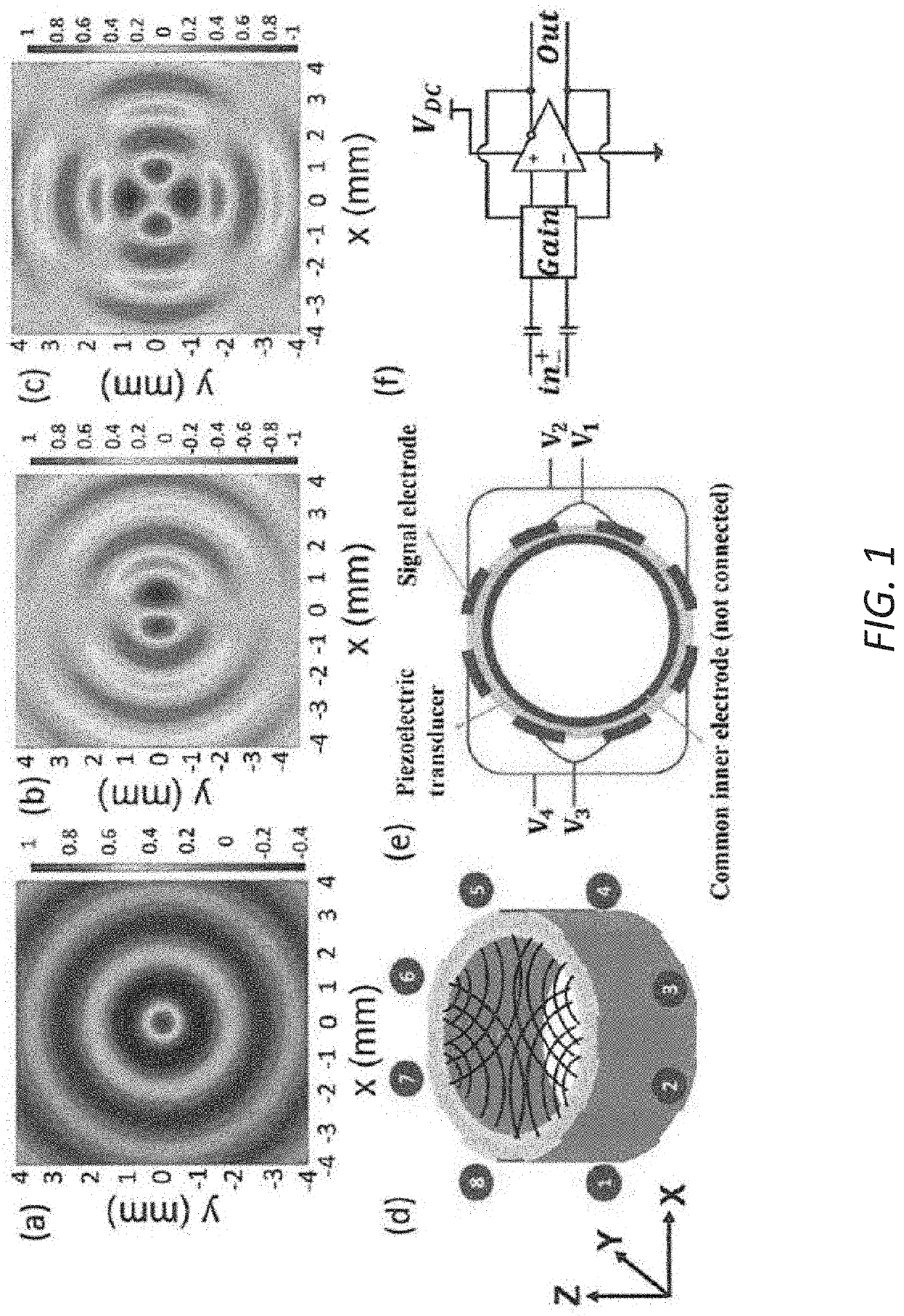
[0016]Creating multiple patterns of pressure interference with a multi-segment ultrasonic transducer array.

[0017]Cylindrical transducers have become an appealing option due to in-phase pressure adding at the center, whose peak can potentially be orders of magnitude larger than one produced by a planar phased array. The propagation of acoustic waves in a cylindrical cavity can be described by solving the wave equation using the separation of variables method subjected to the rigid wall boundary condition in the polar coordinate system. The general acoustic cavity pressure can be written as:

pm,n(r,φ,z)=Jm(krm,nr)·Φm(φ)·eikzz  (1)

where m is the azimuthal mode number.

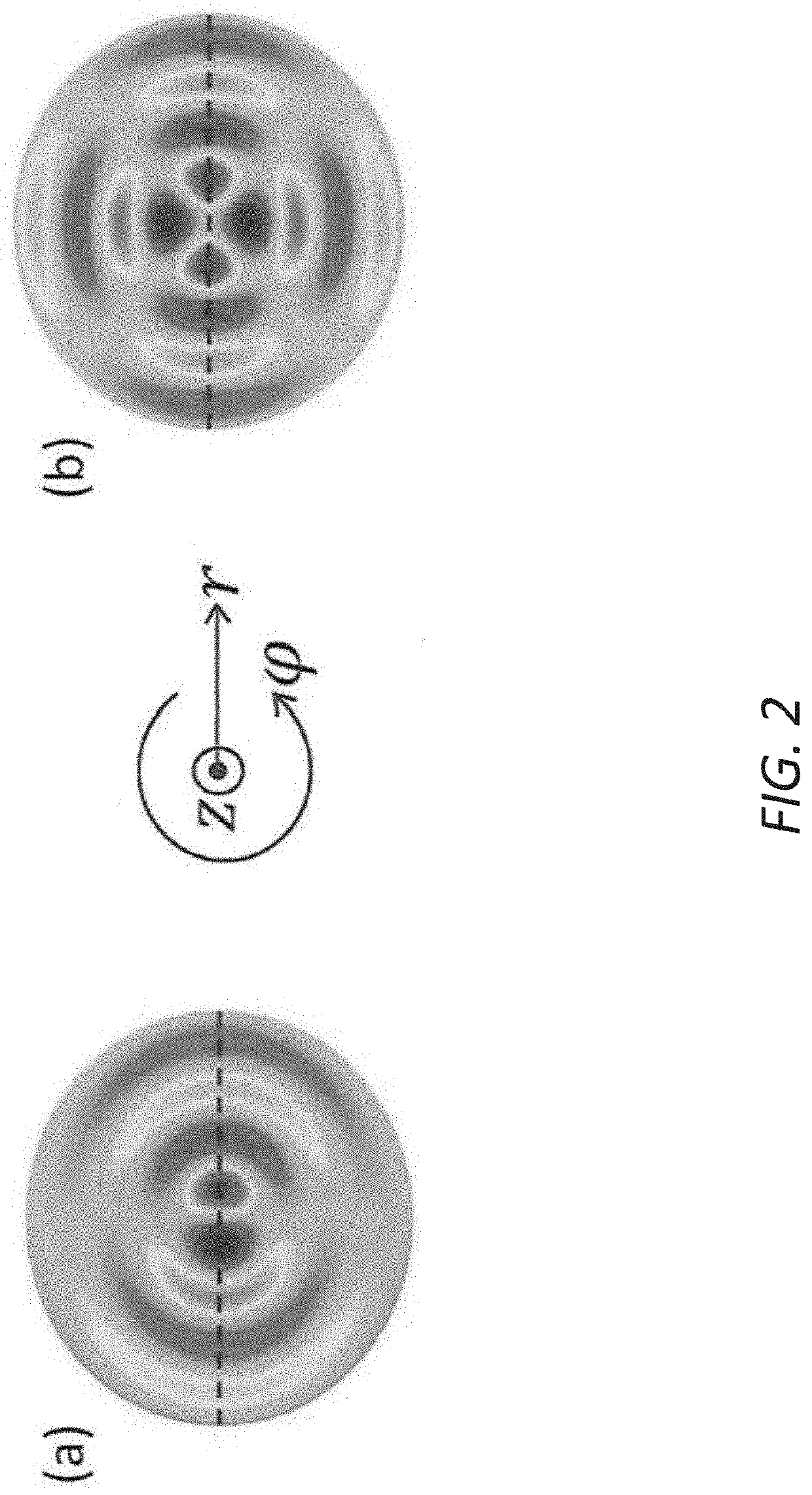
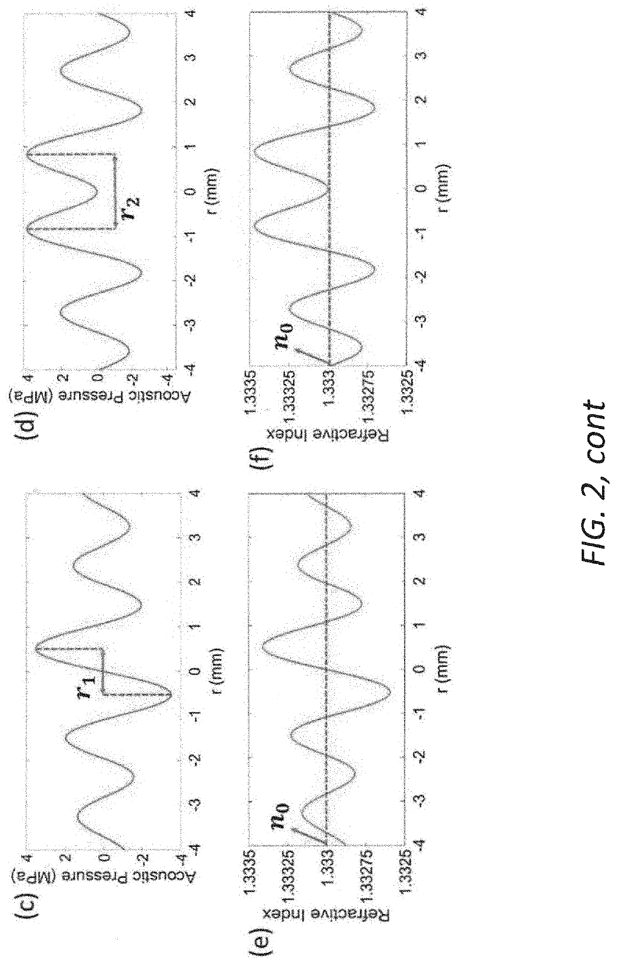
[0018]For each value of m, there will be a sequence of solutions which are characterized as radial modes. The corresponding mode numbers have been denoted by n herein. The pressure variation along the axial direction can be considered negligible because the wave source propagation direction (i.e., the radial direction) is n...


PUM

PropertyMeasurementUnit
diameteraaaaaaaaaa
resonant frequenciesaaaaaaaaaa
frequencyaaaaaaaaaa

Abstract

Disclosed herein is a novel reconfigurable spatial and temporal light modulation method that exploits the imaging medium itself by employing a multi-element ultrasonic transducer array as an in-situ acoustic modulator. The medium density can be modulated using different ultrasonic pressure patterns to pattern an incident collimated beam of light.

Description

RELATED APPLICATIONS[0001]This application claims the benefit of U.S. Provisional Patent Application No. 62 / 764,295, filed Jul. 26, 2018, which is hereby incorporated herein in its entirety.BACKGROUND[0002]Spatial light modulators (SLMs) have major applications in the optics field, including optical signal processing, material processing, laser displays, optical communication and microscopy. To modulate the light spatially, various modalities have been reported in literature such as optically addressed SLMs, acousto-optic (AO) SLMs, and magneto-optic SLMs. These applications require fast beam shaping to achieve high throughput. To meet this criterion, technologies, often under fast feedback control, such as deformable mirrors (OM) and liquid-crystal-based spatial light modulators (LC-SLM), provide fast and active spatial light patterning. However, limitations in the refresh rates (e.g., about 1 kHz for LC-SLM) and number of pixels in each scanning direction (e.g. fast DMs) make them...

Claims


Application Information

Patent Timeline
Patent Type & Authority Patents(United States)
IPC IPC(8): A61N7/00A61B5/00G02F1/125
CPCA61B5/0077A61N7/00G02F1/125A61N2007/006A61N2007/0073
Inventor CHAMANZAR, MAYSAMREZAKARIMI, YASINSCOPELLITI, MATTEO GIUSEPPE
Owner CARNEGIE MELLON UNIV
Why Eureka
Try Eureka