Connector having a sealing member interposed between the connector support member and housing

a technology of sealing member and connector, applied in the direction of coupling base/case, coupling device connection, securing/insulating coupling contact member, etc., can solve the problem of reducing work efficiency and achieve the effect of simplifying manufacturing work

Active Publication Date: 2021-07-13
YAZAKI CORP
View PDF13 Cites 3 Cited by
  • Summary
  • Abstract
  • Description
  • Claims
  • Application Information

AI Technical Summary

Benefits of technology

[0006]An object of the present invention is to provide a connector capable of simplifying manufacturing work.

Problems solved by technology

For example, when an O ring and a stopper are individually attached to each of the conductors, since the amount of work required for the attachment increases, work efficiency may decrease.

Method used


Image

  • Connector having a sealing member interposed between the connector support member and housing
  • Connector having a sealing member interposed between the connector support member and housing
  • Connector having a sealing member interposed between the connector support member and housing

Examples


embodiment

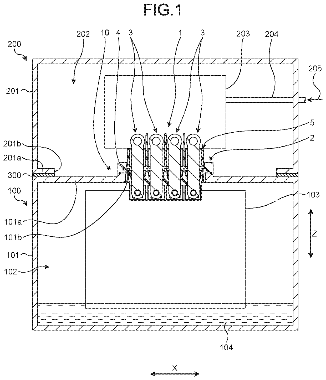
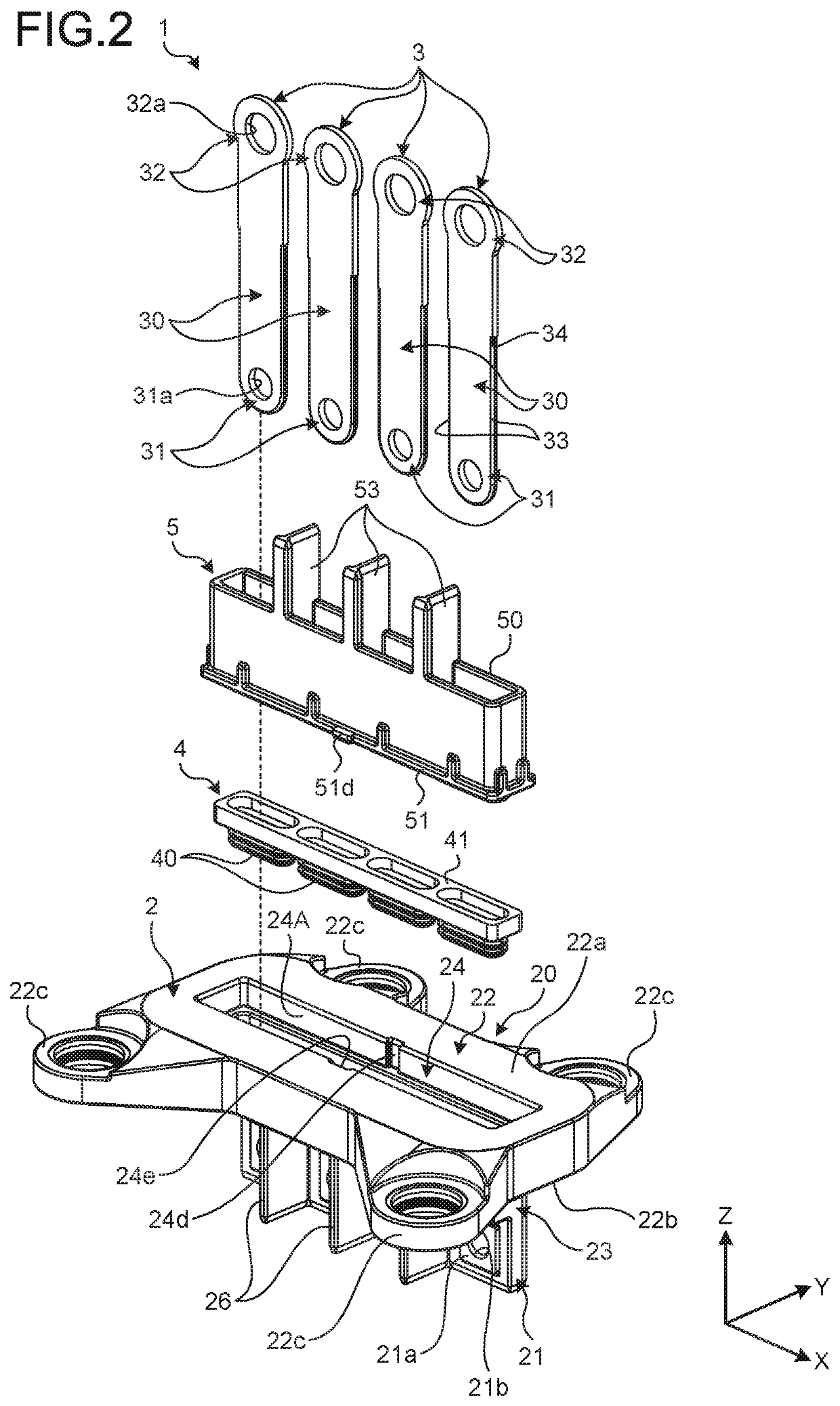
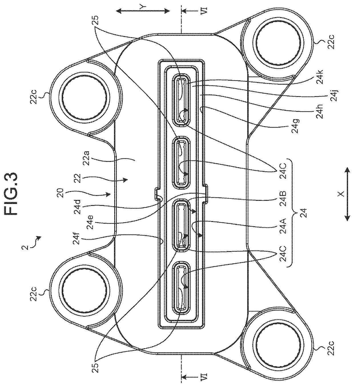
[0037]With reference to FIG. 1 to FIG. 23, the embodiment will be described. The present embodiment relates to a connector. FIG. 1 is a sectional view of a connector, a first device, and a second device according to an embodiment, FIG. 2 is an exploded perspective view of the connector according to the embodiment, FIG. 3 is a plan view of a housing according to the embodiment, FIG. 4 is a front view of the housing according to the embodiment, FIG. 5 is a side view of the housing according to the embodiment, FIG. 6 is a sectional view of the housing according to the embodiment, FIG. 7 is another sectional view of the housing according to the embodiment, FIG. 8 is a front view of a sealing member according to the embodiment, FIG. 9 is a side view of the sealing member according to the embodiment, FIG. 10 is a sectional view of the sealing member according to the embodiment, and FIG. 11 is another sectional view of the sealing member according to the embodiment.

[0038]FIG. 12 is a plan ...

modified examples of embodiment

[0094]The number and shape of the conductors 3 are not limited to the number and shape illustrated in the embodiment. For example, the shape of the conductor 3 may be a shape such as a pin having a circular section. The shapes of the housing 2, the sealing member 4, and the support member 5 are appropriately designed according to the shape of the conductor 3. When a pin having a circular section is used as the conductor 3, the sectional shapes of the first through hole 25 and the second through hole 54 are circular. Furthermore, the sectional shape of the sealing part 40 of the sealing member 4 is circular. The use of the conductor 3 is not limited to a power supply line that supplies electric power, and may be a signal line.

[0095]The shape of the sealing part 40 is not limited to the illustrated shape. Furthermore, the sealing part 40 is not limited to the shaft seal and may be a face seal.

[0096]The insulating wall 53 may be provided in a member different from the support member 5....


PUM


Abstract

A connector includes an insulating housing that is fixed to a casing of a first device at a communication part through which an opening of the casing of the first device and an opening of a casing of a second device communicate with each other and includes first through holes, conductors that are inserted into the respective first through holes to electrically connect the first device and the second device, an insulating sealing member that includes tubular sealing parts that seal between the conductors and the housing, and a connecting part that connects the sealing parts, and an insulating support member that includes second through holes into which the conductors are inserted, is attached to the housing from a side of the second device, and interposes the sealing member between the support member and the housing to support the sealing parts.

Description

CROSS-REFERENCE TO RELATED APPLICATION(S)[0001]The present application claims priority to and incorporates by reference the entire contents of Japanese Patent Application No. 2019-138463 filed in Japan on Jul. 29, 2019.BACKGROUND OF THE INVENTION1. Field of the Invention[0002]The present invention relates to a connector.2. Description of the Related Art[0003]In the related art, a connector having a sealing member is known. Japanese Patent Application Laid-open No. 2018-116896 discloses a technology of a connector including a main housing retaining a main terminal for relaying a main circuit, an electric wire with a connector including an electric wire for relaying a sub-circuit and a sub-connector connected to a terminal of the electric wire, and an electric wire retention part connecting with the main housing and retaining the electric wire.[0004]In the connector of Japanese Patent Application Laid-open No. 2018-116896, the electric wire and the electric wire retention part are sea...

Claims


Application Information

Patent Timeline
Patent Type & Authority Patents(United States)
IPC IPC(8): H01R13/52
CPCH01R13/5205H01R13/5216H01R13/521H01R13/5202H01R13/40H01R13/748H01R2107/00H01R4/34H01R13/502H01R13/42
Inventor AOKI, EIJITAKAHASHI, KAZUHIDE
Owner YAZAKI CORP
Why Eureka
Try Eureka