Method for forming coil

a coil and coil technology, applied in the field of coils, can solve the problems of increasing the space occupied by the coil, increasing the cost of the coil, and the complexity of the manufacturing steps of the coil, so as to achieve high reliability and safety in the electrical characteristic, simplify the manufacturing work of the coil, and high accuracy

Active Publication Date: 2012-01-10
TAMURA KK +1
View PDF12 Cites 6 Cited by
  • Summary
  • Abstract
  • Description
  • Claims
  • Application Information

AI Technical Summary

Benefits of technology

[0048]Also, processes of welding between both the coil elements and the communicating terminal and of folding-back are not required, thereby simplifying the manufacturing work of the coil.
[0049]Furthermore, offset winding is performed based on offset amounts calculated by measuring a positional relation between the second coil element and first coil element during the winding process and, therefore, the accumulation of wire rod feeding errors occurring while each side of the second coil element is formed during the winding process can be cancelled and the arrangement of the first coil element and second coil element can be made highly accurate. This enables, for example, the approximately ling-like core to be reliably inserted in each of the coil elements, thereby providing the coil having high reliability and safety in electrical characteristic.

Problems solved by technology

However, in the first conventional coil described above, the windings to form both the coil elements are coupled via the communicating terminal and, therefore, as described in the above Patent Reference 2, the communicating terminal and the end portion on the coupling side of each of the windings protrude outside from the external shape formed by end surfaces of both the coil elements, resulting in an increase in space occupied by the coil and, when the coil is to be housed in the case described above, in particular, the case becomes the larger in size, thus causing an entire reactor to become large in size.
Moreover, in the above first conventional example of the coil, processes are further required in which coatings on each of the windings and on the end portion on the coupling side of each of the windings are peeled for the connection of both the coil elements and the communicating terminal and, after that, welding is to be performed on these portions, as a result, causing the manufacturing steps of the coil to be very complicated.
Furthermore, in the above first conventional example, the two coil elements each being made up of the individual winding are connected electrically to each other by performing the welding via the communicating terminal and, therefore, it is unavoidable that reliability in the welded portions becomes a problem and still another problem arises that variations occur in electrical characteristics depending on how the welding is performed.
However, in the case of the first conventional example of the coil, the end portions on the coupling side of the two coil elements are coupled via the communicating terminal to each other and, therefore, variations occur readily in the arrangement of the two coil elements, which causes the insertion of the core to become impossible, in some cases.
However, the coupling portion is formed on the end portion side of both the coil elements in a manner in which the coupling portions is folded in half and, as a result, the folded portion unavoidably protrudes on the end portion side of both the coil elements, thus causing an increase in space occupied by the coil in a manner to correspond to the folded portion.
In this case, there is a fear that, if thickness of the folded portion is made to be reduced, electrical characteristics of the winding, that is, of the coil are affected by curvature of the folded portion being made very small.
Also, it cannot be denied that there is a possibility that variations occur in electrical characteristics depending on how the coupling portion is folded.
Furthermore, though the process of performing the welding between both the coil elements and the communicating terminal is made unnecessary, the above-described additional step of folding the coupling portion is required, which presents another problem that the manufacturing processes become complicated.

Method used


Image

  • Method for forming coil
  • Method for forming coil
  • Method for forming coil

Examples


Embodiment Construction

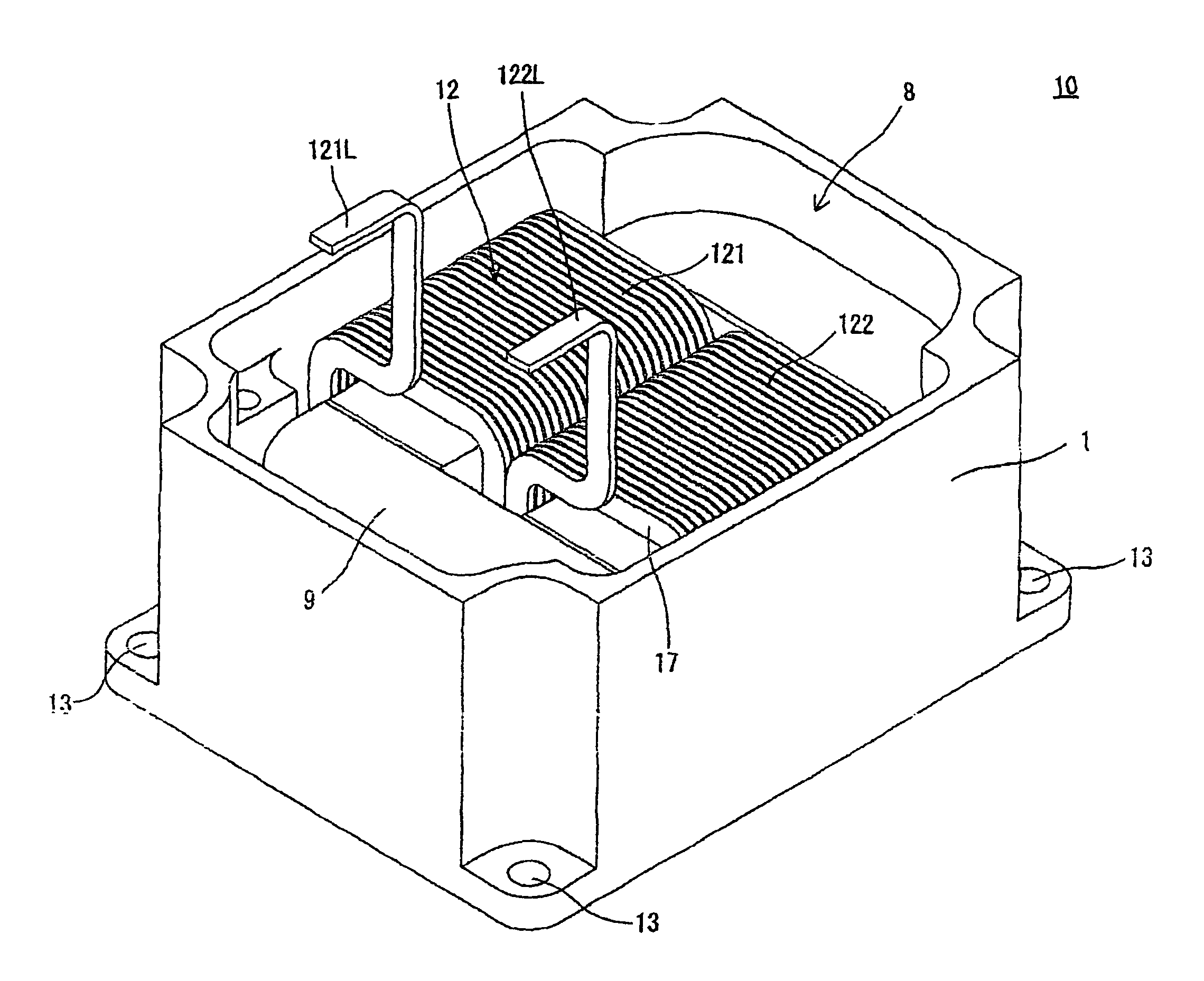
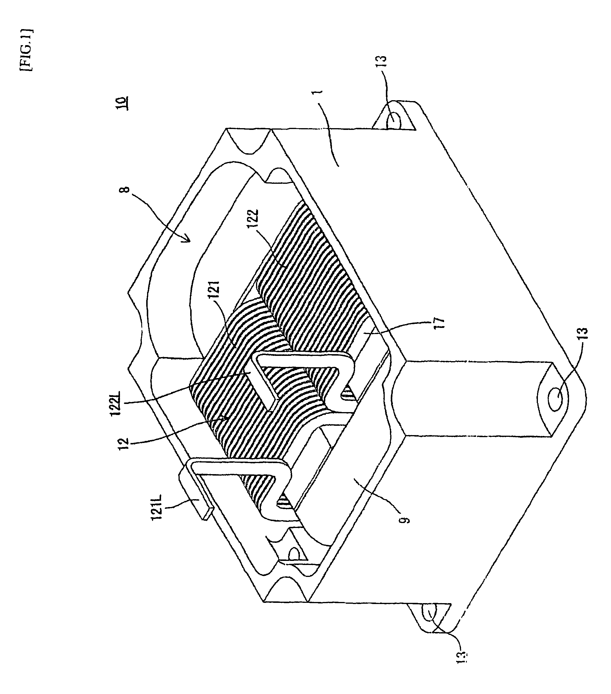
[0060]A coil of the first embodiment of the present invention is described in detail by referring to drawings. According to the first embodiment, the coil of the present invention is applied to a coil of a reactor (hereinafter, referred to as a reactor coil). FIG. 1 is a perspective view of a reactor as one example including the reactor coil of the present invention. The reactor 10 shown in FIG. 1 is used for an electrical circuit in a device having, for example, a forcedly cooling means and is configured so that, after a reactor coil 12 formed by winding one rectangular wire 17 around the reactor core 9 with a bobbin (not shown in FIG. 1) being interposed between the rectangular wire 17, and the reactor coil 12 is housed in a thermal conductive case 1, a filler 8 is poured therein so as to secure the reactor coil 12. Also, as is described later by referring to FIG. 3, the reactor coil 12 of the first embodiment includes the first coil element 121 and second coil element 122 each fo...


PUM

PropertyMeasurementUnit
voltageaaaaaaaaaa
lengthaaaaaaaaaa
inductanceaaaaaaaaaa

Abstract

A reactor coil includes first and second coil elements each formed by edgewise and rectangular winding of one piece of rectangular wire rod in a manner in which the wound rectangular wire rod is stacked rectangularly and cylindrically and, at a winding terminating end point of the first coil element, the rectangular wire rod is bent approximately 90 degrees in a direction opposite to the winding direction of the first coil element so that the rectangular wire rod is stacked in a direction opposite to the stacking direction of the first coil element and is wound edgewisely and rectangularly in a direction opposite to the winding direction of the first coil element to form the second coil element and, as a result, the first coil element and second coil element are aligned in parallel to each other in a continuous state.

Description

BACKGROUND OF THE INVENTION[0001]1. Technical Field[0002]The present invention relates to a coil to be used as an electronic component and a method for forming the coil and more particularly to the coil suitably used as a coil of a reactor and the method for forming the coil.[0003]2. Description of Related Art[0004]In general, a reactor has, for example, a winding and a core made of a magnetic substance and the winding is wound around the core to make up the coil of the reactor, which enables inductance to be obtained. Conventionally, the reactor is used in a voltage boosting circuit, inverter circuit, active filter circuit, or the like, and, in many cases, such the reactor has a structure in which the core and the coil wound around the core are housed, together with other insulating members or the like in a case made of metal or the like (see, for example, Patent Reference 1).[0005]For a reactor to be used in a vehicle-mounted voltage boosting circuit, a coil is used which has a st...

Claims


Application Information

Patent Timeline
Patent Type & Authority Patents(United States)
IPC IPC(8): H01F7/06
CPCH01F27/2847H01F41/0604H01F3/14H01F27/022H01F27/325Y10T29/49073Y10T29/49071Y10T29/4902Y10T29/49069H01F41/061H01F27/28H01F30/00H01F41/06
Inventor HASU, MASATOSHIHATTORI, KAORUNAKATSU, RYOURANO, SEIMAENO, KENSUKE
Owner TAMURA KK
Why Eureka
Try Eureka