Liquid containers having a vent structure promoting improved liquid dispensing

a technology of liquid containers and vents, which is applied in the direction of rigid containers, liquid transferring devices, transportation and packaging, etc., can solve the problems of not being able to achieve the vent structure exhibits one of several shortcomings, and the liquid in the container is not able to be dispensed at the optimal or preferred volumetric flow rate. , to achieve the effect of improving liquid dispensing and ease of operator dispensing, simplifying the vent construction and

Active Publication Date: 2021-12-21
KELLEY PATRICK KEVIN
View PDF30 Cites 0 Cited by
  • Summary
  • Abstract
  • Description
  • Claims
  • Application Information

AI Technical Summary

Benefits of technology

[0006]Embodiments of the present invention are directed to liquid dispensing containers exhibiting improved liquid dispensing and ease of operator dispensing. More specifically, embodiments of the present invention are directed to portable, handheld liquid dispensing containers having a vent structure that provides improved liquid dispensing (e.g., dispensing rate, dispensing uniformity / smoothness, and the like) along with simplified vent construction and container integration. In these regards, embodiments of the present invention advantageously overcome one or more shortcomings associated conventional portable, handheld liquid dispensing containers and other types of containers, facilitating dispensing of liquid contents thereby reducing unwanted and potentially dangerous spillage.
[0012]In one or more embodiments, the longitudinal axis of the vent tube can be skewed with respect to a longitudinal axis of the central passage of the liquid delivery device mounting body such that the first end portion of the vent tube is laterally spaced away from the longitudinal axis of the central passage of the liquid delivery device mounting body by a first distance and the second end portion of the vent tube is laterally spaced away from the longitudinal axis of the central passage of the liquid delivery device mounting body by a second distance less than the first distance to thereby promote draining of liquid from within the central passage of the vent tube into the interior space when the liquid container is in (or near) a surface-supported liquid dispensing position.
[0015]In one or more embodiments, the container support surface upon which the liquid container rests when in a surface-supported liquid dispensing position can define a reference plane extending parallel therewith, the at least one of the walls of the liquid container that comprising the container support surface upon which the liquid container rests when in a surface-supported liquid dispensing position can define a reference plane extending parallel with a surface thereof that partially defines the interior space and the reference plane defined by the container support surface can be skewed with respect to the reference plane defined by the at least one of the walls of the liquid container such that the surface of the at least one of the walls of the liquid container that partially defines the interior space slopes toward the liquid delivery device mounting body to thereby promote draining of liquid from within the interior space through the central passage of the liquid delivery device mounting body when the liquid container is in the surface-supported liquid dispensing position.
[0016]In one or more embodiments, at least one of the walls of the liquid container can comprise a container support surface upon which the liquid container rests when in a surface-supported liquid dispensing position, the central passage of the vent tube can have a longitudinal axis that is approximately straight and the longitudinal axis of the vent tube can be skewed with respect to a reference plane extending parallel with the container support surface such that the first end portion of the vent tube is laterally spaced away from the container support surface by a first distance and the second end portion of the vent tube is laterally spaced away from the container support surface by a second distance less than the first distance to thereby promote draining of liquid from within the central passage of the vent tube into the interior space when the liquid container is in the surface-supported liquid dispensing position.

Problems solved by technology

However, a common problem with many conventional portable, handheld liquid dispensing containers (and other types of liquid dispensing containers) is that the vent tube structure exhibits one of several shortcomings.
One such shortcoming is that the vent structure is prone to allowing liquid to spill from the vent structure during dispensing when the liquid dispensing container is tipped beyond a certain container rotation amount.
Another such shortcoming is that the construction of the vent offers an inadequate volumetric flow of ambient air into the interior space of the container.
This inadequate volumetric flow of ambient air can cause all or a portion of the liquid in the container to not be dispensed in a suitably smooth and uniform liquid flow (e.g., to be dispensed with a “glugging” action) and / or can cause all or a portion of the liquid in the container to be dispensed at a less than optimal or preferred volumetric flow rate.
Still another such shortcoming is that the construction of the vent is cumbersome to fabricate and / or integrate into the container.
The inability of the user to precisely position the dispensing container relative to the receiving container during such pouring often contributes to spilling of contents of the dispensing container during pouring.

Method used


Image

  • Liquid containers having a vent structure promoting improved liquid dispensing
  • Liquid containers having a vent structure promoting improved liquid dispensing
  • Liquid containers having a vent structure promoting improved liquid dispensing

Examples


Embodiment Construction

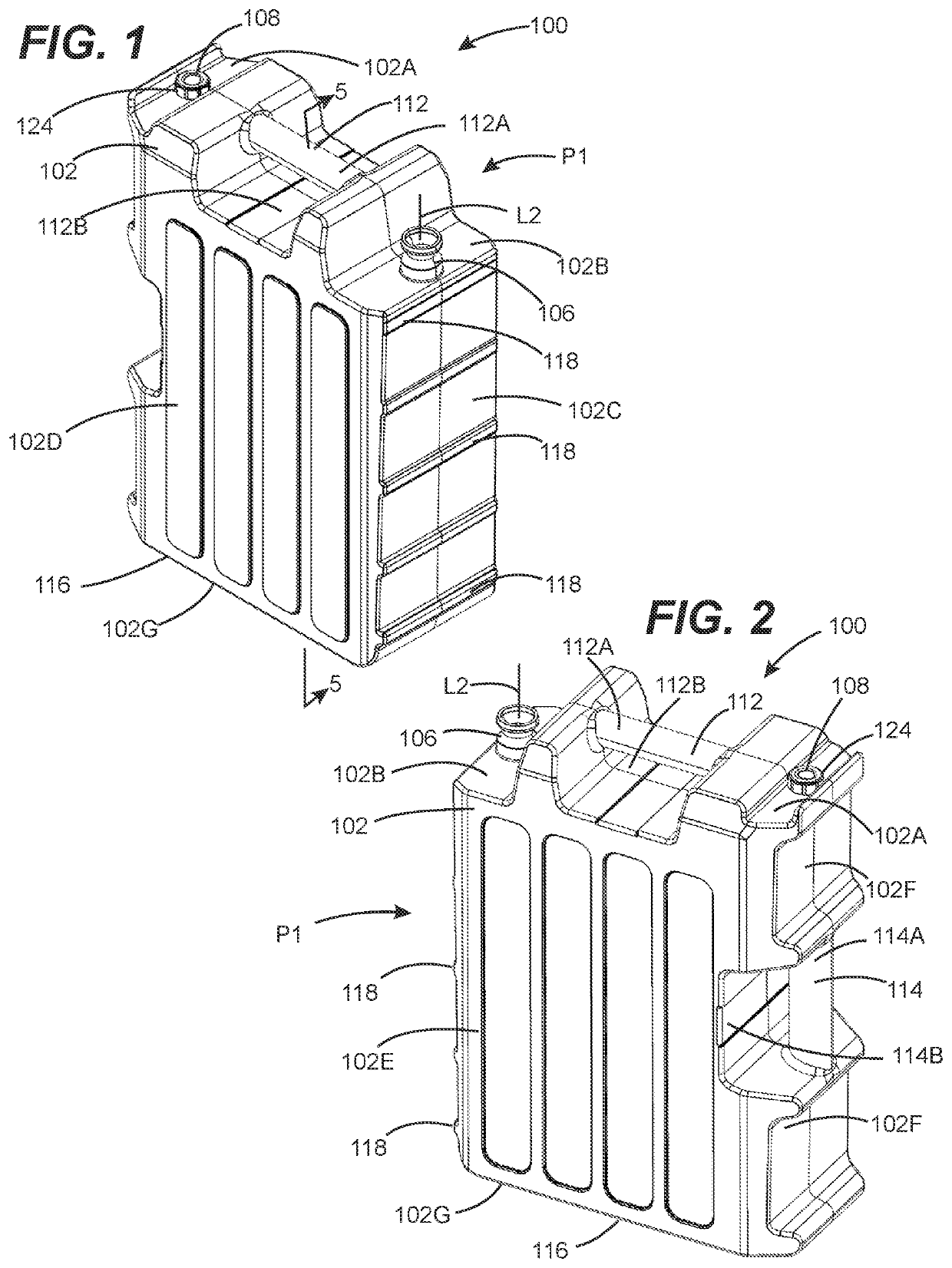
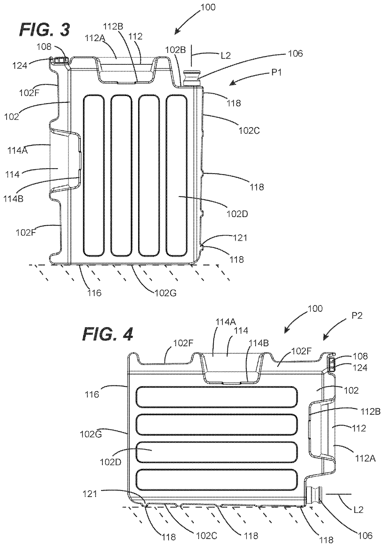
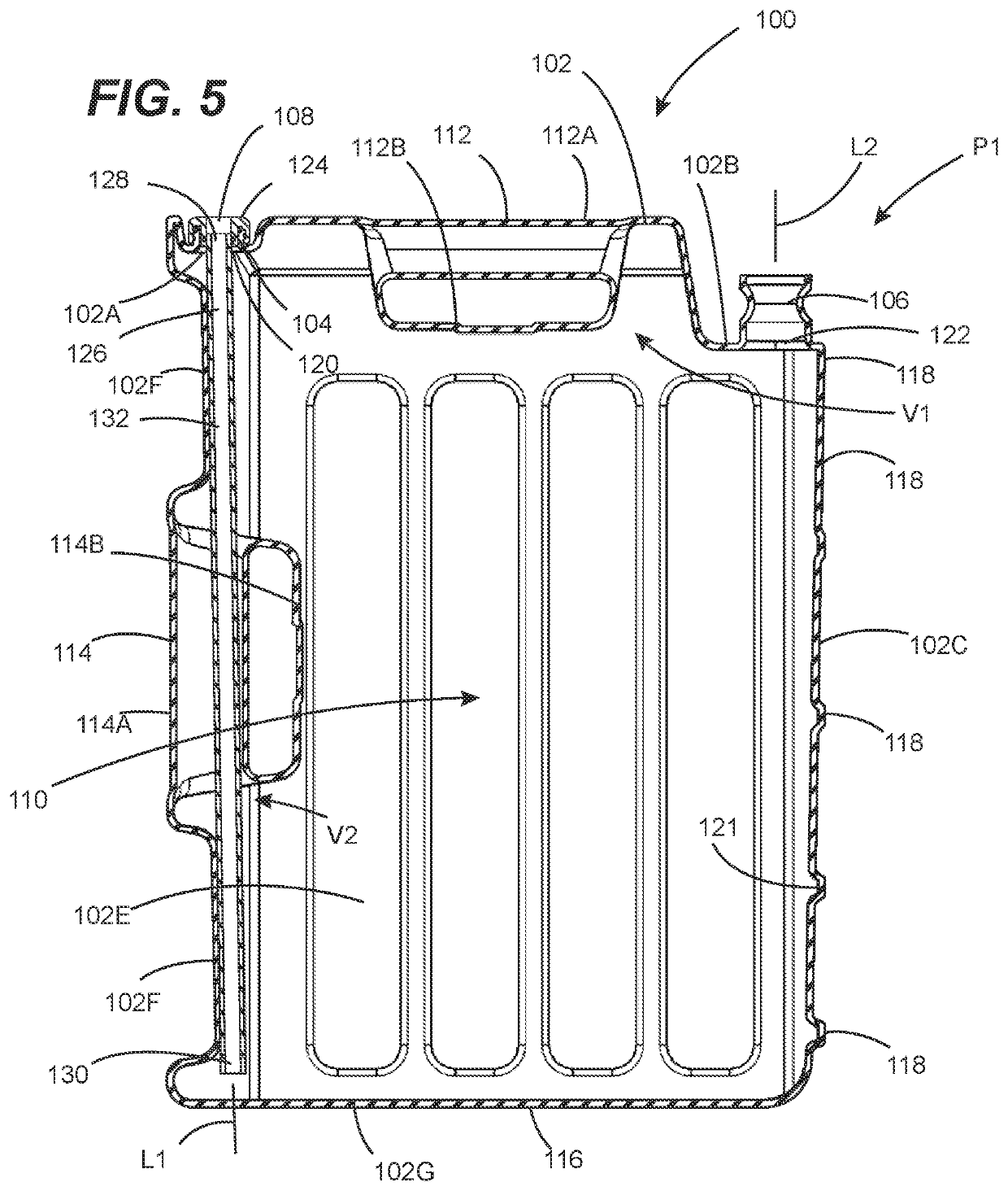
[0025]Referring to FIGS. 1-5, a liquid dispensing container configured in accordance with one or more embodiment of the present invention is shown (i.e., the liquid dispensing container 100). As shown, the liquid dispensing container 100 is a portable, handheld liquid dispensing container. However, in one or more other embodiments, the liquid dispensing container 100 can be a non-portable and / or non-handheld liquid dispensing container. Advantageously, the liquid dispensing container 100 possesses a vent structure that provides improved liquid dispensing along with simplified vent construction and container integration. In these regards, the liquid dispensing container 100 advantageously overcomes one or more shortcomings associated conventional portable, handheld liquid dispensing containers and other types of containers.

[0026]The liquid dispensing container 100 comprises a liquid container 102 (including a plurality of walls 102A-102G), a vent tube mounting body 104, a liquid deli...


PUM


Abstract

Disclosed herein are embodiments of liquid dispensing container preferably configured as portable, handheld liquid dispensing containers. These liquid dispensing containers possesses a vent structure that provides improved liquid dispensing along with simplified vent construction and container integration. In these regards, these liquid dispensing containers advantageously overcome one or more shortcomings associated conventional liquid dispensing containers and other types of containers.

Description

CROSS-REFERENCE TO RELATED APPLICATIONS[0001]This continuation patent application claims priority from co-pending United States Non-Provisional patent application having Ser. No. 17 / 073,609, filed 19 Oct. 2020, entitled “LIQUID CONTAINERS HAVING A VENT STRUCTURE PROMOTING IMPROVED LIQUID DISPENSING”, having a common applicant herewith and being incorporated herein in its entirety by reference.FIELD OF THE DISCLOSURE[0002]The disclosures made herein relate generally to liquid dispensing containers and, more particularly, to liquid dispensing containers having a vent structure promoting improved liquid dispensing.BACKGROUND[0003]It is well known that portable, handheld liquid dispensing containers are a type of liquid dispensing container that are available and useful in a number of shapes and sizes, and are made for a number of purposes. Such liquid dispensing containers are also well known to be useful for transporting and dispensing various types of liquids. Examples of these liqui...

Claims


Application Information

Patent Timeline
Patent Type & Authority Patents(United States)
IPC IPC(8): B65D47/32B65D25/28B67D7/32
CPCB65D47/32B65D25/2897B67D7/3227B65D25/2894
Inventor KELLEY, PATRICK KEVINALDRIDGE, CHRISTOPHER BARLOW
Owner KELLEY PATRICK KEVIN
Why Eureka
Try Eureka