Liquid containers having a vent structure promoting improved liquid dispensing

Active Publication Date: 2021-03-02
P KELLEY PLLC
View PDF30 Cites 0 Cited by
  • Summary
  • Abstract
  • Description
  • Claims
  • Application Information

AI Technical Summary

Benefits of technology

The present invention provides improved liquid dispensing and ease of operator dispensing for portable, handheld liquid dispensing containers. Specifically, embodiments of the invention have a vent structure that promotes better liquid dispensing along with simplified construction and integration with the container. The vent tube has a skewed longitudinal axis that allows the liquid to flow smoothly and evenly through the vent during dispensing. Additionally, the container support surface and walls help to promote draining of the liquid when it is surface-supported. These improvements help to reduce spillage and make the liquid dispensing process more efficient.

Problems solved by technology

However, a common problem with many conventional portable, handheld liquid dispensing containers (and other types of liquid dispensing containers) is that the vent tube structure exhibits one of several shortcomings.
One such shortcoming is that the vent structure is prone to allowing liquid to spill from the vent structure during dispensing when the liquid dispensing container is tipped beyond a certain container rotation amount.
Another such shortcoming is that the construction of the vent offers an inadequate volumetric flow of ambient air into the interior space of the container.
This inadequate volumetric flow of ambient air can cause all or a portion of the liquid in the container to not be dispensed in a suitably smooth and uniform liquid flow (e.g., to be dispensed with a “glugging” action) and / or can cause all or a portion of the liquid in the container to be dispensed at a less than optimal or preferred volumetric flow rate.
Still another such shortcoming is that the construction of the vent is cumbersome to fabricate and / or integrate into the container.
The inability of the user to precisely position the dispensing container relative to the receiving container during such pouring often contributes to spilling of contents of the dispensing container during pouring.

Method used


Image

  • Liquid containers having a vent structure promoting improved liquid dispensing
  • Liquid containers having a vent structure promoting improved liquid dispensing
  • Liquid containers having a vent structure promoting improved liquid dispensing

Examples


Embodiment Construction

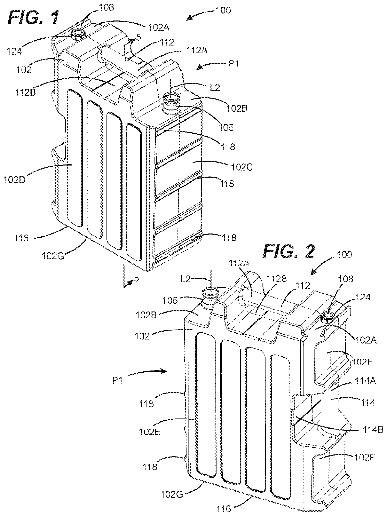
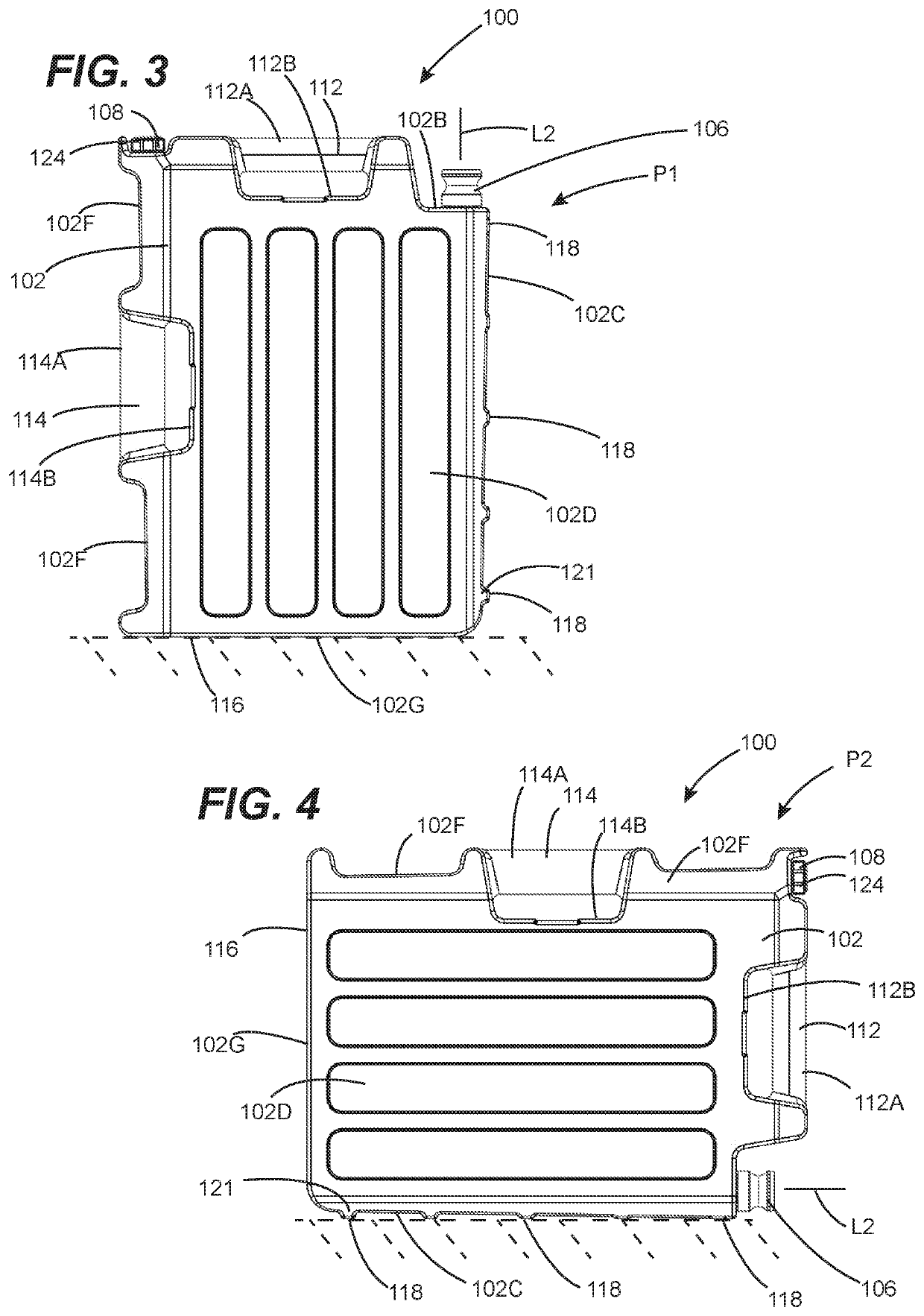
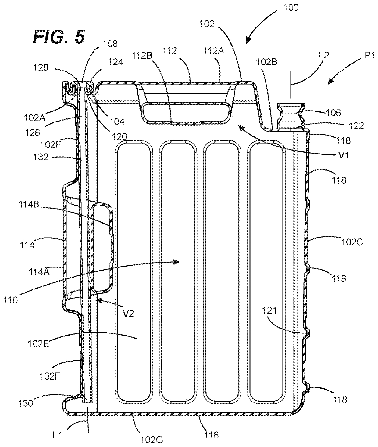
[0025]Referring to FIGS. 1-5, a liquid dispensing container configured in accordance with one or more embodiment of the present invention is shown (i.e., the liquid dispensing container 100). As shown, the liquid dispensing container 100 is a portable, handheld liquid dispensing container. However, in one or more other embodiments, the liquid dispensing container 100 can be a non-portable and / or non-handheld liquid dispensing container. Advantageously, the liquid dispensing container 100 possesses a vent structure that provides improved liquid dispensing along with simplified vent construction and container integration. In these regards, the liquid dispensing container 100 advantageously overcomes one or more shortcomings associated conventional portable, handheld liquid dispensing containers and other types of containers.

[0026]The liquid dispensing container 100 comprises a liquid container 102 (including a plurality of walls 102A-102G), a vent tube mounting body 104, a liquid deli...


PUM


Abstract

Disclosed herein are embodiments of liquid dispensing container preferably configured as portable, handheld liquid dispensing containers. These liquid dispensing containers possesses a vent structure that provides improved liquid dispensing along with simplified vent construction and container integration. In these regards, these liquid dispensing containers advantageously overcome one or more shortcomings associated conventional liquid dispensing containers and other types of containers.

Description

FIELD OF THE DISCLOSURE[0001]The disclosures made herein relate generally to liquid dispensing containers and, more particularly, to liquid dispensing containers having a vent structure promoting improved liquid dispensing.BACKGROUND[0002]It is well known that portable, handheld liquid dispensing containers are a type of liquid dispensing container that are available and useful in a number of shapes and sizes, and are made for a number of purposes. Such liquid dispensing containers are also well known to be useful for transporting and dispensing various types of liquids. Examples of these liquids include, but are not limited to, fuels, lubricants, water and the like.[0003]It is desirable for liquid within an interior space of a portable, handheld liquid dispensing container to be dispensable through a dispensing structure of the container in a relatively smooth and uniform liquid flow. To this end, portable, handheld liquid containers include a vent structure that allows dispensed l...

Claims


Application Information

Patent Timeline
IPC IPC(8): B65D47/32B67D7/32B65D25/28
CPCB65D47/32B65D25/2897B67D7/3227B65D25/2894
Inventor KELLEY, PATRICK KEVINALDRIDGE, CHRISTOPHER BARLOW
Owner P KELLEY PLLC
Why Eureka
Try Eureka