Foldable electronic device including magnets

a technology of electronic devices and magnets, applied in the direction of magnetic bodies, identification means, instruments, etc., can solve the problems of lowering the magnetic force, the closed state of foldable electronic devices is not maintained, and the foldable electronic devices are not closed well

Active Publication Date: 2021-12-21
SAMSUNG ELECTRONICS CO LTD
View PDF9 Cites 0 Cited by
  • Summary
  • Abstract
  • Description
  • Claims
  • Application Information

AI Technical Summary

Benefits of technology

[0006]An aspect of the disclosure is to provide an electronic device that maintains a sufficient force of attraction between magnets, even if the temperature of the magnets (or the temperature around the magnets) changes, thereby providing a consistent manipulation experience to a user during operation of folding the electronic device.

Problems solved by technology

However, the temperature of the electronic device, more specifically, the temperature around the magnets may increase due to heat generated by the electronic device or changes in the external environment (e.g., an increase in ambient temperature, user gripping, and the like), thereby lowering the magnetic force.
This may also cause a problem in that the foldable electronic device is not closed well or the folded state thereof is not maintained due to the reduced force of attraction between the magnets.
If magnets having relatively high magnetic force are used, a problem may arise in that the foldable electronic device does not easily open due to the high force of attraction between the magnets at a relatively low temperature.

Method used


Image

  • Foldable electronic device including magnets
  • Foldable electronic device including magnets
  • Foldable electronic device including magnets

Examples


Embodiment Construction

[0030]Various embodiments of the disclosure will now be described in detail with reference to the accompanying drawings. In the following description, specific details such as detailed configuration and components are merely provided to assist the overall understanding of these embodiments of the disclosure. Therefore, it should be apparent to those skilled in the art that various changes and modifications of the embodiments described herein can be made without departing from the scope and spirit of the disclosure. In addition, descriptions of well-known functions and constructions are omitted for clarity and conciseness.

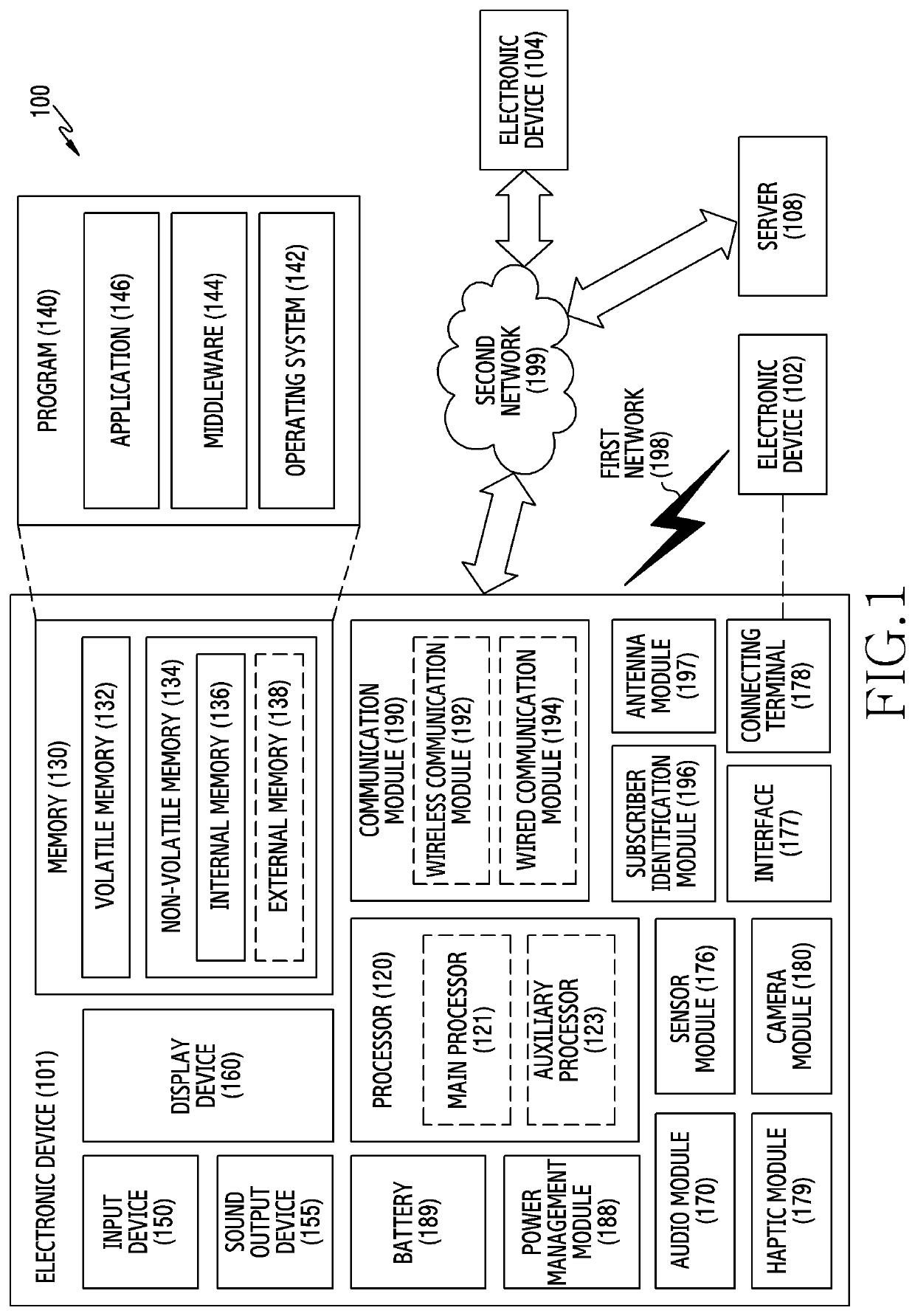
[0031]FIG. 1 illustrates an electronic device in a network environment according to an embodiment.

[0032]Referring to FIG. 1, the electronic device 101 in the network environment 100 may communicate with an electronic device 102 via a first network 198 (e.g., a short-range wireless communication network), or an electronic device 104 or a server 108 via a second netwo...


PUM

PropertyMeasurementUnit
angleaaaaaaaaaa
narrow angleaaaaaaaaaa
flexibleaaaaaaaaaa

Abstract

An electronic device is provided, which includes a first housing, a second housing, a hinge structure, a flexible display configured to form a front surface of the first housing and the second housing while the electronic device is in an unfolded state, a first support member disposed between the flexible display and the first housing, a first bimetal member disposed between the flexible display and the first support member, a first magnet disposed between the flexible display and the first bimetal member, and a second magnet disposed between the flexible display and the second housing. The first bimetal member has a first length at a first temperature and a second length longer than the first length at a second temperature higher than the first temperature. The first support member has a reception space having a length greater than or equal to the first length and less than the second length that provides space for the first bimetal member to bend at the second temperature.

Description

CROSS-REFERENCE TO RELATED APPLICATION(S)[0001]This application is based on and claims priority under 35 U.S.C. § 119 to Korean Patent Application No. 10-2019-0094354, filed on Aug. 2, 2019, in the Korean Intellectual Property Office, the entire disclosure of which is incorporated herein by reference.BACKGROUND1. Field[0002]The disclosure relates generally to a foldable electronic device including magnets.2. Description of Related Art[0003]A flexible display, unlike a flat display, may be folded or bent.[0004]Using a flexible display, a foldable electronic device capable of being folded may be manufactured. A foldable electronic device may include a hinge structure and may be capable of an operation in which the flexible display is folded about the hinge structure.[0005]Magnets may be provided inside a foldable electronic device in order to maintain the folded state of the foldable electronic device. However, the temperature of the electronic device, more specifically, the temperatu...

Claims


Application Information

Patent Timeline
Patent Type & Authority Patents(United States)
IPC IPC(8): G06F1/16H01F7/02
CPCG06F1/1616G06F1/1652G06F1/1656G06F1/1681H01F7/02H01F7/0226H01F7/0263G09F9/301F16C11/04H04M1/0216H01F7/00
Inventor CHO, WOOSIKKIM, TAEWON
Owner SAMSUNG ELECTRONICS CO LTD
Why Eureka
Try Eureka