Eureka AIR delivers breakthrough ideas for toughest innovation challenges, trusted by R&D personnel around the world.

Centrifugal compressor and turbocharger

a centrifugal compressor and turbocharger technology, applied in the direction of machines/engines, liquid fuel engines, combustion air/fuel air treatment, etc., can solve the problem of additional flow loss, and achieve the effect of suppressing the reduction of compressor efficiency

Active Publication Date: 2022-07-05
MITSUBISHI HEAVY IND ENGINE & TURBOCHARGER LTD
View PDF21 Cites 0 Cited by
  • Summary
  • Abstract
  • Description
  • Claims
  • Application Information

AI Technical Summary

Benefits of technology

[0045]At least one embodiment of the present invention provides a centrifugal compressor and a turbocharger whereby it is possible to suppress a reduction in compressor efficiency due to the configuration of the connection portion between the bypass passage and the compressor inlet pipe.

Problems solved by technology

The provision of the bypass valve enables active control near the surge line but causes additional flow loss at a branch portion formed between the scroll passage and the bypass passage.

Method used


Image

  • Centrifugal compressor and turbocharger
  • Centrifugal compressor and turbocharger
  • Centrifugal compressor and turbocharger

Examples


Embodiment Construction

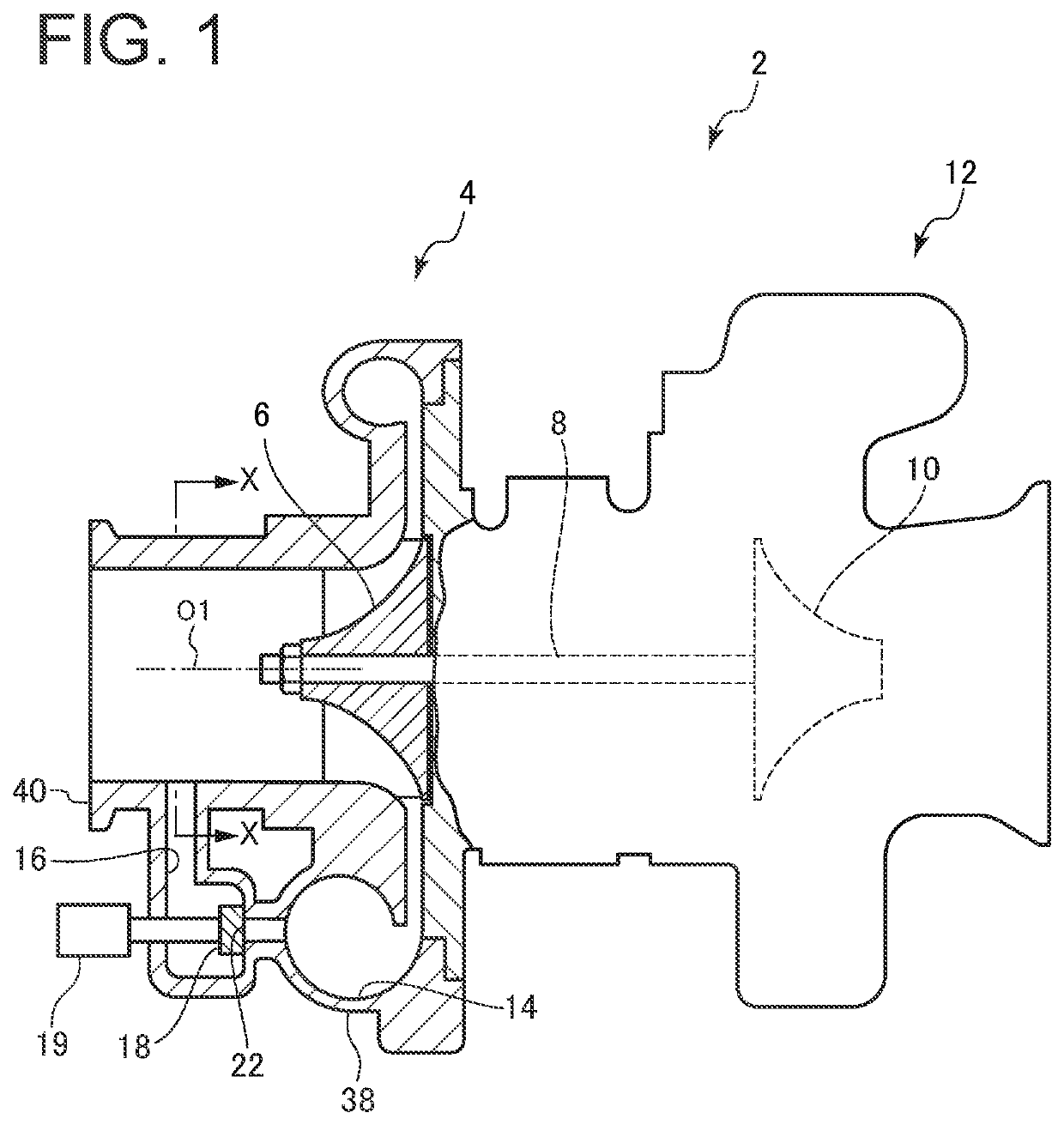
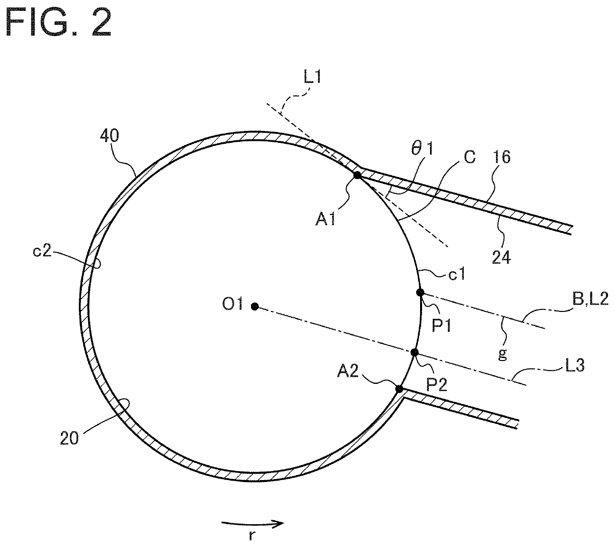
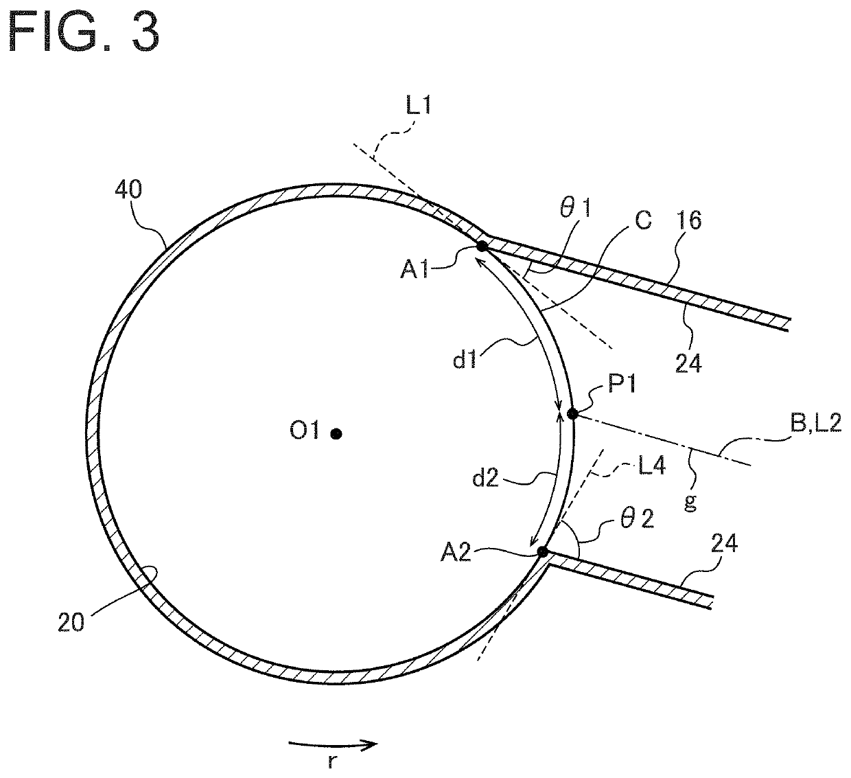
[0062]Embodiments of the present invention will now be described in detail with reference to the accompanying drawings. It is intended, however, that unless particularly identified, dimensions, materials, shapes, relative positions, and the like of components described in the embodiments shall be interpreted as illustrative only and not intended to limit the scope of the present invention.

[0063]For instance, an expression of relative or absolute arrangement such as “in a direction”, “along a direction”, “parallel”, “orthogonal”, “centered”, “concentric” and “coaxial” shall not be construed as indicating only the arrangement in a strict literal sense, but also includes a state where the arrangement is relatively displaced by a tolerance, or by an angle or a distance whereby it is possible to achieve the same function.

[0064]For instance, an expression of an equal state such as “same”“equal” and “uniform” shall not be construed as indicating only the state in which the feature is stric...


PUM


Abstract

A centrifugal compressor includes an impeller, a compressor inlet pipe for guiding air to the impeller, a scroll passage disposed on an outer peripheral side of the impeller, and a bypass passage connecting the compressor inlet pipe and the scroll passage and bypassing the impeller. In a cross-section perpendicular to an axis of the compressor inlet pipe, when A1 is a connection portion on a downstream side in a rotational direction of the impeller of connection portions between an inner wall surface of the compressor inlet pipe and an inner wall surface of the bypass passage, C is a virtual circle constituting the inner wall surface of the compressor inlet pipe, and L1 is a tangent line of the virtual circle C at the connection portion A1, the inner wall surface of the bypass passage is formed from the connection portion A1 along the tangent line L1.

Description

TECHNICAL FIELD[0001]The present disclosure relates to a centrifugal compressor and a turbocharger.BACKGROUND ART[0002]In a turbocharger used in, for example, passenger cars, a bypass valve may be used as a device for avoiding surging caused by a rapid decrease in flow rate during engine deceleration. In this case, the bypass valve is provided on a bypass passage that connects a compressor inlet pipe and a scroll passage, and the bypass valve is opened at an operating point at a high pressure ratio near the surge line to reduce the boost pressure and ensure a predetermined surge margin.[0003]The provision of the bypass valve enables active control near the surge line but causes additional flow loss at a branch portion formed between the scroll passage and the bypass passage.[0004]Patent Document 1 proposes that the surface of the valve body of the bypass valve is shaped along the inner wall of the scroll passage of the compressor. With this structure, it is possible to suppress an i...

Claims


Application Information

Patent Timeline
Patent Type & Authority Patents(United States)
IPC IPC(8): F04D29/42F04D29/44F04D17/10
CPCF04D29/4213F04D29/441F04D17/10F04D29/4253F05D2220/40F05D2250/51Y02T10/12F02B37/162F02B33/40F02M35/10157F02M35/10144F02M35/10262F04D27/0215
Inventor HAYASHI, YOSHIHIROFUJITA, YUTAKAIWAKIRI, KENICHIRO
Owner MITSUBISHI HEAVY IND ENGINE & TURBOCHARGER LTD
Why Eureka
Eureka Blog
Learn More