3D eyewear adapted for facial geometry

a facial geometry and projection system technology, applied in the field of three-dimensional projection systems, can solve the problems of reducing optical efficiency, crosstalk between the right eye and the left eye filter, and system utilizing spectral separation, so as to minimize wavelength shifting, short nose bridges, and long nose bridges

Active Publication Date: 2022-07-12
DOLBY LAB LICENSING CORP
View PDF26 Cites 0 Cited by
  • Summary
  • Abstract
  • Description
  • Claims
  • Application Information

AI Technical Summary

Benefits of technology

[0005]The inventors have discovered that certain problems of the prior art are exacerbated for viewers with certain facial geometries, for example nose bridge length and brow position. Problems of the prior art are overcome by providing eyewear that provides a quality 3D viewing experience for both viewers with relatively long nose bridges and viewers with relatively short nose bridges. The design of eyewear considers differing facial geometries of viewers and minimizes wavelength shifting that can result therefrom.
[0008]The one or more positioning surfaces limit the distance between the left lens and the left eye of the wearer and the distance between the right lens and the right eye of the wearer to a minimum distance in the range of 15-20 mm. The positioning surfaces thereby prevent the lenses from being positioned too close the wearers eyes, which can exacerbate the angular obliqueness at which light passes through the lenses, thereby increasing a wavelength shift of filter properties for that light.
[0013]The example method additionally includes fixing some of the left and right lenses into the frames of the first plurality of frames, and fixing others of the left and right lenses into the frames of the second plurality of frames. The example method facilitates using similar lenses in different frames for viewers with different facial geometries.

Problems solved by technology

Systems utilizing spectral separation have problems.
This shift changes the wavelengths of the light that are either passed or blocked by the filter, and can cause crosstalk between the right eye and left eye filters and a reduction in optical efficiency.
Previous solutions include curving the filters to minimize off axis incidence; however, this solution is not ideal in every situation.
The inventors have discovered that certain problems of the prior art are exacerbated for viewers with certain facial geometries, for example nose bridge length and brow position.

Method used


Image

  • 3D eyewear adapted for facial geometry
  • 3D eyewear adapted for facial geometry
  • 3D eyewear adapted for facial geometry

Examples


Embodiment Construction

[0028]The present invention overcomes the problems associated with the prior art, by providing three dimensional (3D) eyewear that is suited for users of varying facial geometries. In the following description, numerous specific details are set forth (e.g., widths of spectral bands, lens characteristics, etc.) in order to provide a thorough understanding of the invention. Those skilled in the art will recognize, however, that the invention may be practiced apart from these specific details. In other instances, details of well-known 3D projection practices (e.g., image generation and filtering) and components have been omitted, so as not to unnecessarily obscure the present invention.

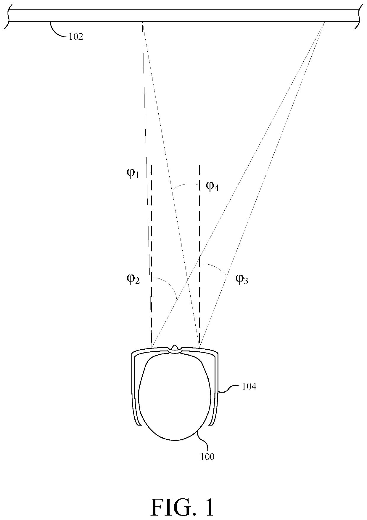
[0029]FIG. 1 shows a viewer 100 viewing a 3D projection screen 102 through a pair of 3D glasses 104. Light composing 3D images reflects off screen 102 and enters the eyes of viewer 100 through lenses (not visible) built into a pair of 3D glasses 104. The lenses spectrally filter the light to pass only li...


PUM


Abstract

Three dimensional (3D) glasses suited for wearers with varying facial geometries may include a frame adapted to position spectrally filtering lenses at a particular distance from the eyes of the wearer. The 3D glasses may include a means for adjusting the distance between the lenses and the eyes of the wearer. The lenses may include positive runout.

Description

CROSS-REFERENCE TO RELATED APPLICATION[0001]This application is a national stage application, filed under 35 U.S.C. § 371, of International Patent Application No. PCT / US2017 / 053679, filed on Sep. 27, 2017, and claims the benefit of priority from U.S. Provisional Patent Application No. 62 / 402,964 filed Sep. 30, 2016, each of which is hereby incorporated by reference in its entirety.BACKGROUND OF THE INVENTIONField of the Invention[0002]This invention relates generally to three-dimensional (3D) projection systems, and more particularly to eyewear for use with 3D projection systems.Description of the Background Art[0003]3D projection systems are known. 3D images are created by forming separate right and left eye images with varying depths of field. The 3D images are typically filtered through some form of eyewear to ensure the right eye receives only the right eye images and the left eye receives only the left eye images. One example method of 3D imaging is spectral separation. Systems...

Claims


Application Information

Patent Timeline
Patent Type & Authority Patents(United States)
IPC IPC(8): G02B30/00G02B30/23G02C5/12G02B5/28
CPCG02B30/23G02B5/285G02C5/122G02C5/126
Inventor LIPPEY, BARRETRICHARDS, MARTIN J.HUANG, CHRISTOPHER L.HOVANKY, THAOALLEN, WILSON HEATON
Owner DOLBY LAB LICENSING CORP
Why Eureka
Try Eureka