Electrospinning method

a technology of electropinning and electrodes, applied in the field of electropinning devices, can solve the problems of not always desirable to have a non-woven or aligned structur

Active Publication Date: 2022-09-13
INNOVATIVE MECHANICAL ENG TECH BV
View PDF12 Cites 0 Cited by
  • Summary
  • Abstract
  • Description
  • Claims
  • Application Information

AI Technical Summary

Benefits of technology

[0013]By directing a laser beam towards the collecting surface of an electrospinning device, different parts of the fibrous structure can be targeted without the need for removing the fibrous structure from the collector, which normally leads to an unwanted deformation of the fibrous structure. As a result, predefined parts of the electrospun structure can be removed in a controlled and steered / programmable way. This results in a very accurate patterning in the fibrous structure. By removing predefined parts of the fibrous structure, the structure stiffness and / or transparency can be accurately changed for a multitude of applications.
[0019]By interrupting the laser beam for a moment and directing the laser beam towards another location, the laser beam will produce a number of cutouts or holes. This enables the manufacturing repetitive cutout or holes and as such of more complex patterns in the fibrous structure.
[0021]Optionally, the laser ablating takes place during the actual electrospinning process. In this way delamination of the various layers is prevented. Delamination may occur when performing the laser processing ‘offline’. It is noted that this unwanted delamination of the electrospun fibrous layers can happen already when the electrospinning process is stopped for a very short period of time.

Problems solved by technology

This requires an accurate steering and positioning of the fiber which is very complex up to the point of not even possible.
For application of electrospun structures, among others biological applications, it is not always desirable to have a non-woven or aligned structure at the micro-level in relation to the overall form and performance of the macro structure.

Method used


Image

  • Electrospinning method
  • Electrospinning method
  • Electrospinning method

Examples


Embodiment Construction

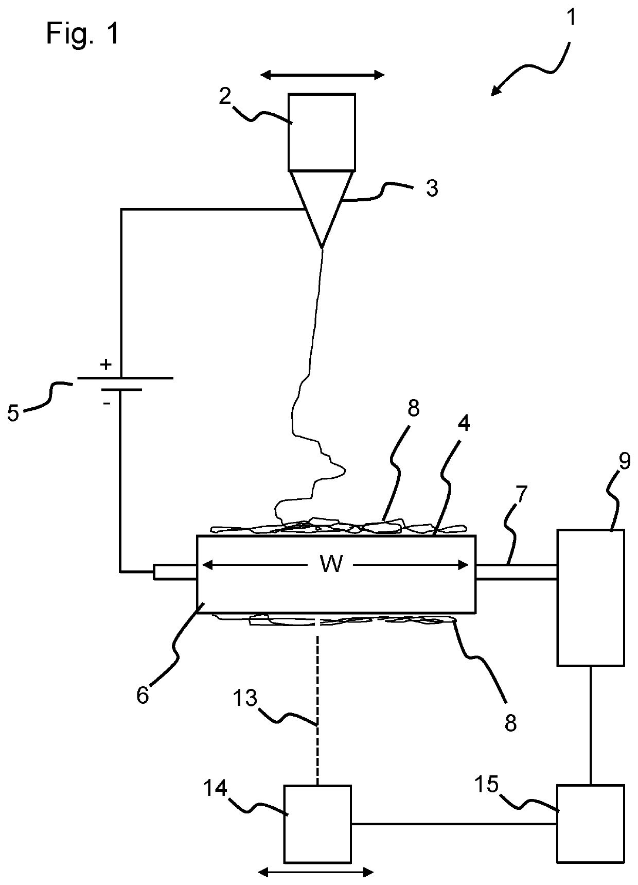
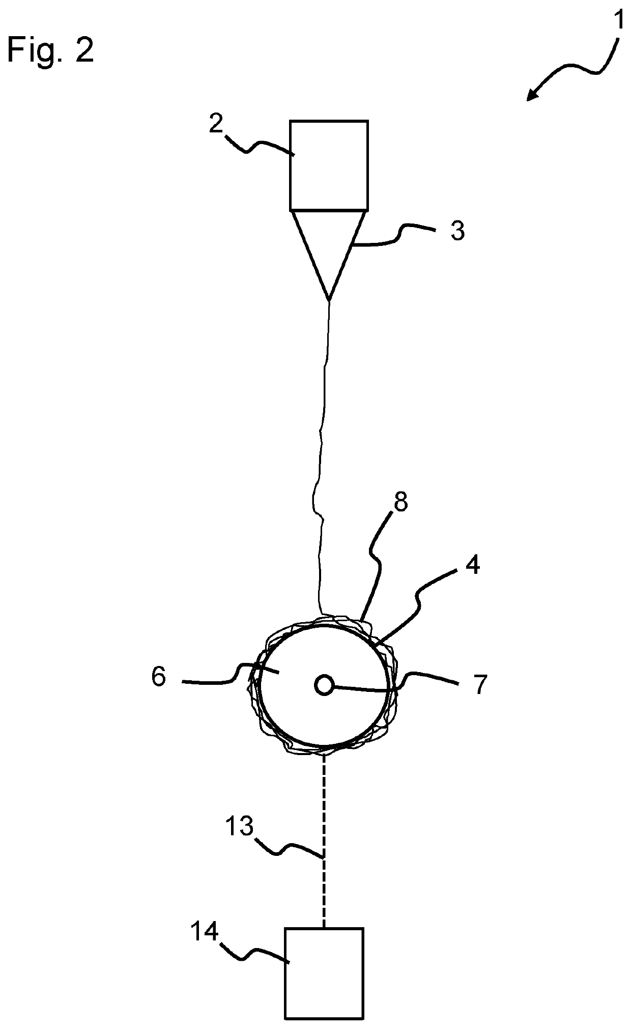
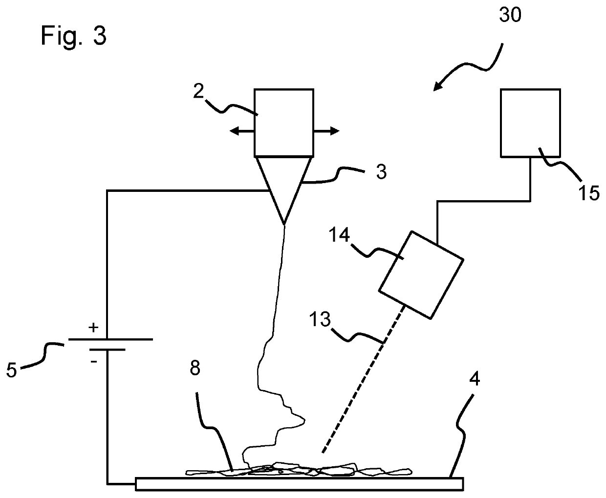
[0054]FIG. 1 schematically shows an embodiment of an electrospinning device 1. The electrospinning device 1 may be arranged inside an enclosure (not shown in FIG. 1) for quality or security reasons. The electrospinning device 1 may comprise a container 2 for holding a liquid comprising a polymer melt or a polymer solution, and a nozzle 3 arranged to outlet a stream of the liquid from the container 2. The electrospinning device 1 further comprises a rotating collector 6 with a collecting surface 4 for collecting electro spun material coming from the nozzle 3 during an electrospinning process. A voltage supply system 5 may be arranged to create a voltage difference between the nozzle 3 and the collecting surface 4. The voltage supply system 5 may comprise at least one AC or DC voltage supply to create the voltage difference or it may comprise two voltage supplies, one creating a voltage difference between the collecting surface 4 and ground and one creating a difference between the no...


PUM

PropertyMeasurementUnit
angleaaaaaaaaaa
angleaaaaaaaaaa
voltageaaaaaaaaaa

Abstract

A method of electrospinning (40) is provided, and an electrospinning device (1; 30). The method comprises (i) holding (41) a liquid comprising a polymer melt or a polymer solution in a container (2), (ii) letting out (42) a stream of the liquid from the container through at least one nozzle (3), (iii) creating (43) a voltage difference between the nozzle (3) and a collecting surface (4), (iv) collecting (44) electro spun material coming from the nozzle (3) so as to form a fibrous structure (8) on the collecting surface (4), and (v) directing (45) a laser beam (13) towards the collecting surface (4) so as to locally remove a part of the fibrous structure (8).

Description

FIELD OF THE INVENTION[0001]The invention relates to an electrospinning device for producing a fibrous structure. The invention also relates to method of electrospinning.BACKGROUND ART[0002]Electrospinning is a method to produce continuous fibers with a diameter ranging from a few tens of nanometers to a few tens of micrometers. To electrospin fibers, a suitable liquefied material may be fed through a small nozzle. The liquefied material may be electrically charged by applying a high voltage between the nozzle and a counter electrode. The generated electric field causes a cone-shape deformation of the droplet at the nozzle tip. Once the surface tension of this droplet is overcome by the electrical force, a jet is formed out of the droplet and a fiber forms that moves towards the counter electrode. During the flight towards the counter electrode the fiber is continuously stretched and elongated by the different forces acting on it, reducing its diameter and allowing it to solidify by...

Claims


Application Information

Patent Timeline
Patent Type & Authority Patents(United States)
IPC IPC(8): B29C41/26D01D7/00D04H3/02D04H3/07D01D5/00D04H3/073D06M10/00B29C69/00B29C35/08
CPCD01D5/0076B29C69/001D01D5/0038D01D5/0046D01D5/0092D04H3/073D06M10/005B29C2035/0838B29C2791/009B29C2793/009B29C2793/0045D10B2509/022D10B2509/06D01D5/0061
Inventor JANSSEN, PAUL JOHANNES FRANCISCUS MARIASIMONET, MARCSOLBERG, RAMON HUBERTUS MATHIJS
Owner INNOVATIVE MECHANICAL ENG TECH BV
Why Eureka
Try Eureka