Electromagnetic stirring device
a technology of stirring device and magnetic field, which is applied in the direction of mixing, transportation and packaging, chemistry apparatus and processes, etc., can solve problems such as deterioration in product quality
- Summary
- Abstract
- Description
- Claims
- Application Information
AI Technical Summary
Benefits of technology
Problems solved by technology
Method used
Image

Examples
example 1
[0088]A result of an electromagnetic field analysis simulation performed for confirming the flow generated in the molten steel 2 in the mold 30 in this embodiment is described.
(Simulation 1)
[0089]Various simulation conditions were set as described below, and the electromagnetic field analysis simulation was performed regarding each of the electromagnetic stirring device 100 according to this embodiment and an electromagnetic stirring device 900 according to a comparative example.
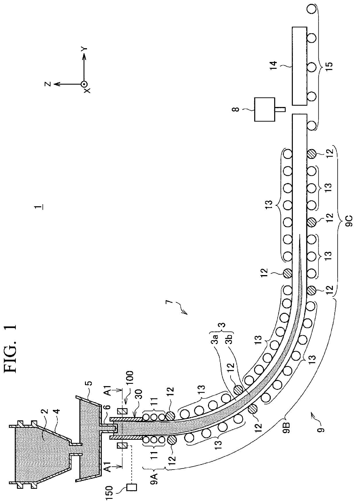
[0090]Herein, the electromagnetic stirring device 900 according to the comparative example is described with reference to FIG. 6. FIG. 6 is a top cross-sectional view illustrating the electromagnetic stirring device 900 according to the comparative example. Specifically, FIG. 6 is a cross-sectional view taken along line A1-A1 in FIG. 1 in a case where the electromagnetic stirring device 900 is applied in place of the electromagnetic stirring device 100 to the continuous casting machine 1.
[0091]The electromag...
example 2
[0136]A result of an actual machine test performed to confirm a quality of a bloom manufactured in this embodiment is described. Specifically, an electromagnetic stirring device having a similar configuration as that of the electromagnetic stirring device 100 according to this embodiment described above was installed in a continuous casting machine actually used in operation (having a similar configuration as that of the continuous casting machine 1 illustrated in FIG. 1), and continuous casting was performed while variously changing a value of a current frequency of an alternating current applied to a coil 130. A surface quality and an internal quality of a bloom obtained after casting were examined by visual inspection and ultrasonic flaw detection inspection. Conditions for continuous casting are as follows.
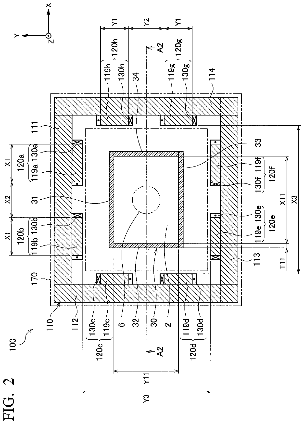
[0137]Width X11 in long side direction of bloom: 456 mm
[0138]Width Y11 in short side direction of bloom: 339 mm
[0139]Thickness T11 of mold plate: 25 mm
[0140]Width X1 in long s...
example 3
[0160]A result of a heat flow analysis simulation performed for confirming in further detail the flow generated in the molten steel 2 in the mold 30 in this embodiment is described.
(Simulation 1)
[0161]Using a result of distribution of the electromagnetic force applied to the molten steel 2 obtained by the above-described electromagnetic field analysis simulation for the electromagnetic stirring device 100 according to this embodiment performed while setting the current frequency to 1.2 Hz, the heat flow analysis was performed.
[0162]Conditions of the heat flow analysis simulation regarding this embodiment are as follows.
[0163]Width X11 in long side direction of bloom: 456 mm
[0164]Width Y11 in short side direction of bloom: 339 mm
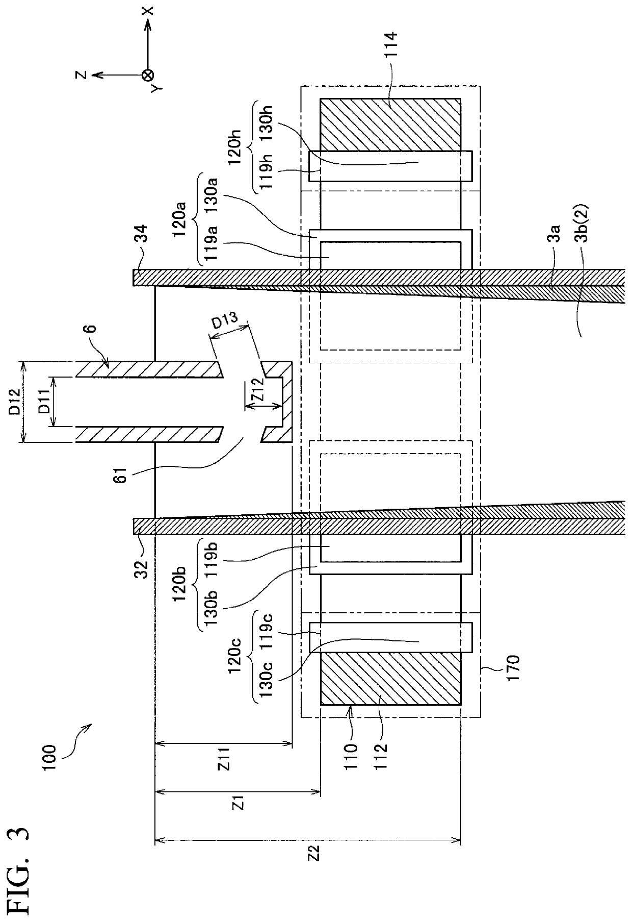
[0165]Distance Z11 in vertical direction between bottom surface of immersion nozzle 6 and bath level of molten steel 2: 250 mm
[0166]Inner diameter D11 of immersion nozzle 6: 90 mm
[0167]Outer diameter D12 of immersion nozzle 6: 145 mm
[0168]Height Z12 from bott...
PUM
| Property | Measurement | Unit |
|---|---|---|
| size | aaaaa | aaaaa |
| width | aaaaa | aaaaa |
| width | aaaaa | aaaaa |
Abstract
Description
Claims
Application Information
 - R&D
- Intellectual Property
- Life Sciences
- Materials
- Tech Scout
- Unparalleled Data Quality
- Higher Quality Content
- 60% Fewer Hallucinations
Browse by: Latest US Patents, China's latest patents, Technical Efficacy Thesaurus, Application Domain, Technology Topic, Popular Technical Reports.
© 2025 PatSnap. All rights reserved.Legal|Privacy policy|Modern Slavery Act Transparency Statement|Sitemap|About US| Contact US: help@patsnap.com