Electronic abacus

a technology of electronic abacus and guide parts, applied in mechanical digital computers, instruments, digital computers, etc., can solve the problems of reducing productivity, long time for mounting each guide member, complicated manufacturing process, etc., and achieves the effect of simple and easy assembly

Active Publication Date: 2022-11-15
SON BUM SUK
View PDF8 Cites 0 Cited by
  • Summary
  • Abstract
  • Description
  • Claims
  • Application Information

AI Technical Summary

Benefits of technology

[0014]An electronic abacus according to the present invention is advantageous in that abacus beads fitted on each support rod can be mounted on an abacus bead moving member simultaneously, and the removal of moving members can be prevented even when the moving members lean to one side by tilting an abacus frame, thus making it simpler and easier to assemble.

Problems solved by technology

However, such a configuration is problematic in that the abacus bead itself or an interior of the abacus bead should be formed of a magnet to detect the position and movement of the abacus bead, so that a manufacturing process is complicated and productivity is lowered.
Meanwhile, the electronic abacus of the above-described configuration is problematic in that the guide member is individually mounted on each row to correspond to detecting units arranged in a plurality of rows on a printed circuit board, so that it takes a long time to mount each guide member.
In this case, light is introduced to thereby hinder the detection of a sensor.
Particularly, the structure shown in FIG. 4 of the cited document is problematic in that the abacus bead moving member and the abacus bead should be aligned with each other on each guide member so as to fit each abacus bead into the insert slot of the moving member, so that the assembly work is slow and cumbersome.
Furthermore, since the screen provided on each moving member is almost equal in width to the support plate located at an upper position, the screen may obstruct another sensor even by slight misalignment, thus causing malfunction.
However, in this case, the support plate located at the upper position is too heavy compared to the screen located at a lower position.
Hence, for example, when the moving members lean to one side by tilting the abacus frame so as to fit the abacus beads fitted on the support rod on the moving members simultaneously, the moving members that are heavy on upper portions thereof may spill out from a state in which they are fitted into the guide members, so that the assembly work becomes slower and more cumbersome.
Thus, since the work of matching the position of the abacus bead with that of the moving member should be performed, the assembly work is likewise slow and cumbersome.

Method used


Image

  • Electronic abacus
  • Electronic abacus
  • Electronic abacus

Examples


Embodiment Construction

[0022]Hereinafter, details and advantages of the present invention will be described in detail with reference to embodiments of the invention shown in the accompanying drawings.

[0023]In the description of the embodiments of the invention, parts other than essential parts are not illustrated and described. Like reference numerals designate like elements throughout the specification, and detailed description thereof will not be repeated.

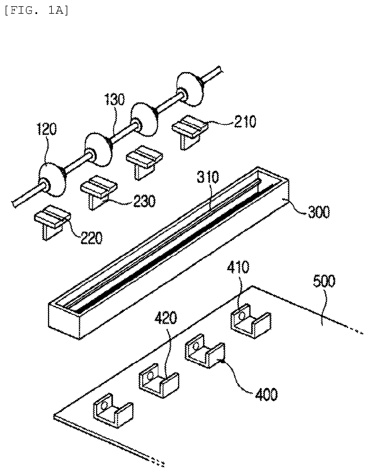
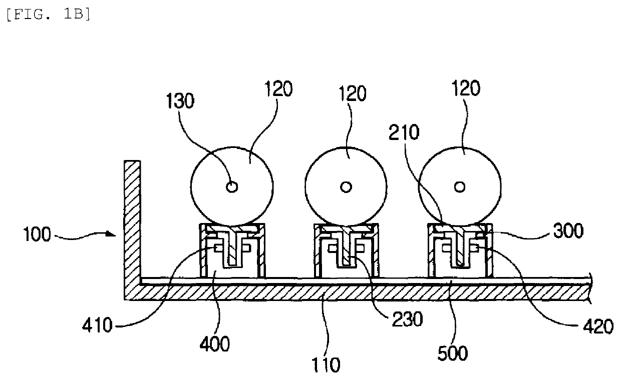
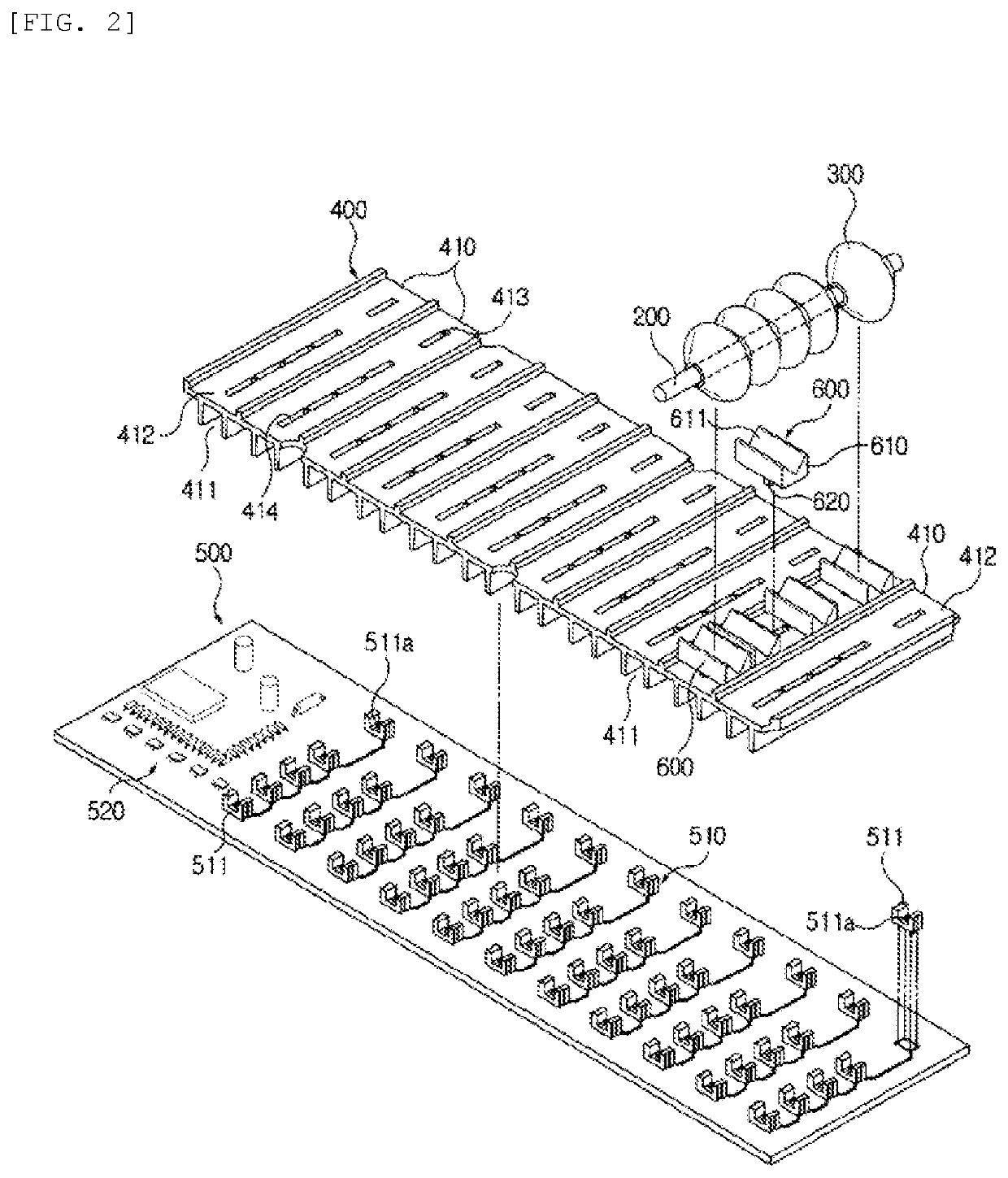
[0024]FIG. 2 is a perspective view showing the internal configuration of an electronic abacus according to the present invention, FIG. 3 shows a plan view, a bottom view, and a front view of an abacus bead guide panel shown in FIG. 2, FIG. 4 shows side views illustrating various shapes of an abacus bead moving member shown in FIG. 2, and FIG. 5 shows sectional views illustrating the assembled state and the use state of the electronic abacus according to the present invention.

[0025]The main components of the electronic abacus according to the present in...


PUM


Abstract

The present invention relates to an electronic abacus including: a plurality of abacus beads fitted on each of unit-specific support rods mounted on an abacus frame to be slidable in a vertical direction; an abacus bead position detecting unit including a plurality of position detecting means for detecting a position change of each abacus bead from lower parts of the abacus beads fitted on each of the unit-specific support rods; an abacus bead guide panel in which unit-specific guide blocks for guiding movement of the abacus beads fitted on each of the unit-specific support rods are integrally connected to cover all of the abacus bead position detecting unit; and a plurality of abacus bead moving members provided in a number which is the same as that of the abacus beads in the guide panel to movably support the abacus beads fitted on each of the support rods.

Description

TECHNICAL FIELD[0001]The present invention relates to an electronic abacus. More particularly, the present invention relates to an electronic abacus that is simple and convenient to assemble.BACKGROUND ART[0002]Generally, an electronic abacus is operated as follows: when a user moves an abacus bead positioned on each support rod, a magnet positioned in the abacus bead moves to generate a magnetic field, and the generated magnetic field is detected by a sensing means positioned in a lower surface of the electronic abacus, so that the movement of the abacus bead is detected. After the position of the abacus bead detected by the sensing means is converted into a digital signal and calculation information depending on the movement of the abacus bead and the position of the support rod is analyzed by an analyzing means, the analyzed data is transmitted through an USB connection port to a computer.[0003]However, such a configuration is problematic in that the abacus bead itself or an inte...

Claims


Application Information

Patent Timeline
Patent Type & Authority Patents(United States)
IPC IPC(8): G06C1/00G09B19/02
CPCG06C1/00G09B19/02
Inventor SON, BUM SUK
Owner SON BUM SUK
Why Eureka
Try Eureka