One-piece optical fiber adapter

a technology of optical fiber and adapter, applied in the field of optical fiber adapters, can solve the problems of time-consuming assembly, and achieve the effect of fewer parts, simple and easy assembly

Active Publication Date: 2015-12-01
LIN SUNG AN +1
View PDF13 Cites 1 Cited by
  • Summary
  • Abstract
  • Description
  • Claims
  • Application Information

AI Technical Summary

Benefits of technology

[0011]The present disclosure provides an optical fiber adapter that has fewer parts and is simpler and easier to assemble.

Problems solved by technology

Furthermore, the adapter 200 has more parts and therefore is time-consuming to assemble.

Method used


Image

  • One-piece optical fiber adapter
  • One-piece optical fiber adapter
  • One-piece optical fiber adapter

Examples


Embodiment Construction

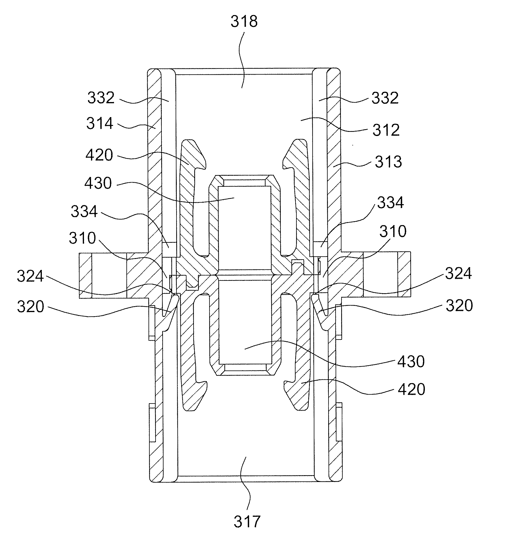
[0029]Referring to FIGS. 3a to 3g, the optical fiber adapter according to the present disclosure includes a unitary molded plastic main body 300. The main body 300 is substantially rectangular and has an passage 315 defined by a top wall 311, a bottom wall 312, a right wall 313 and a left wall 314, wherein the top wall 311 faces the bottom wall 312 and connects with the right wall 313 and left wall 314. The passage 315 has opposing first opening 317 and second opening 318 in an axial direction through which an optical fiber connector may be inserted into the passage 315. Two elastic plates 320 are formed at the right wall 313 and left wall 314 respectively, wherein one extends from the right wall 313 toward the left wall 314 and the second opening 318, and the other extends from the left wall 314 toward the right wall 313 and the second opening 318. Specifically, the elastic plates 320 have roots 322 and rear ends324, respectively. One of the elastic plates 320 extends from the root...


PUM

PropertyMeasurementUnit
elasticaaaaaaaaaa
structureaaaaaaaaaa
distanceaaaaaaaaaa

Abstract

The optical fiber adapter of the present disclosure includes a main body and a pair of inner housings. The main body has a passage defined by a first wall, a second wall, a third wall and a fourth wall. The passage has opposing first and second openings in an axial direction. A first stop block is positioned on the first wall. A second stop block is positioned on the third wall. A first elastic plate and a second elastic plate are positioned within the passage. The inner housings are positioned within the passage, wherein the inner housing includes a flange and a hollow cylinder extending from the flange. The flanges of the two inner housings are attached to each other and are positioned between the first stop block and first elastic plate, and between the second stop block and second elastic plate.

Description

CROSS REFERENCE TO RELATED APPLICATION[0001]The present application is based on and claims priority to Taiwanese Application Number 103100784, filed Jan. 9, 2014, the disclosure of which is hereby incorporated by reference herein in its entirety.BACKGROUND[0002]1. Technical Field[0003]The disclosure relates to an optical fiber adapter, and more particularly, to a one-piece optical fiber adapter.[0004]2. Description of the Related Art[0005]Referring to FIG. 1, a conventional SC type one-piece optical fiber adapter 10 includes a main body 11. The main body 11 has an accommodation room 32 defined by a plurality of side-walls 60, wherein the accommodation room 32 is configured to receive an optical fiber connector 90. When the optical fiber connector 90 is inserted into the accommodation room 32 of the optical fiber adapter 10, a key protrusion 92 on the connector 90 will be received in a guiding slot 30 on one side-wall 60. In addition, the optical fiber adapter 10 further includes a s...

Claims


Application Information

Patent Timeline
Patent Type & Authority Patents(United States)
IPC IPC(8): G02B6/38
CPCG02B6/3807G02B6/3825G02B6/3874Y10T29/49826
Inventor LIN, SUNG-ANLIN, SUNG-CHI
Owner LIN SUNG AN
Why Eureka
Try Eureka