Dial gauge
a dial gauge and dial gauge technology, applied in the direction of measurement gauges, measuring apparatus bearings/suspensions, instruments, etc., can solve the problem of deteriorating measurement accuracy
- Summary
- Abstract
- Description
- Claims
- Application Information
AI Technical Summary
Problems solved by technology
Method used
Image
Examples
first embodiment
[First Embodiment]
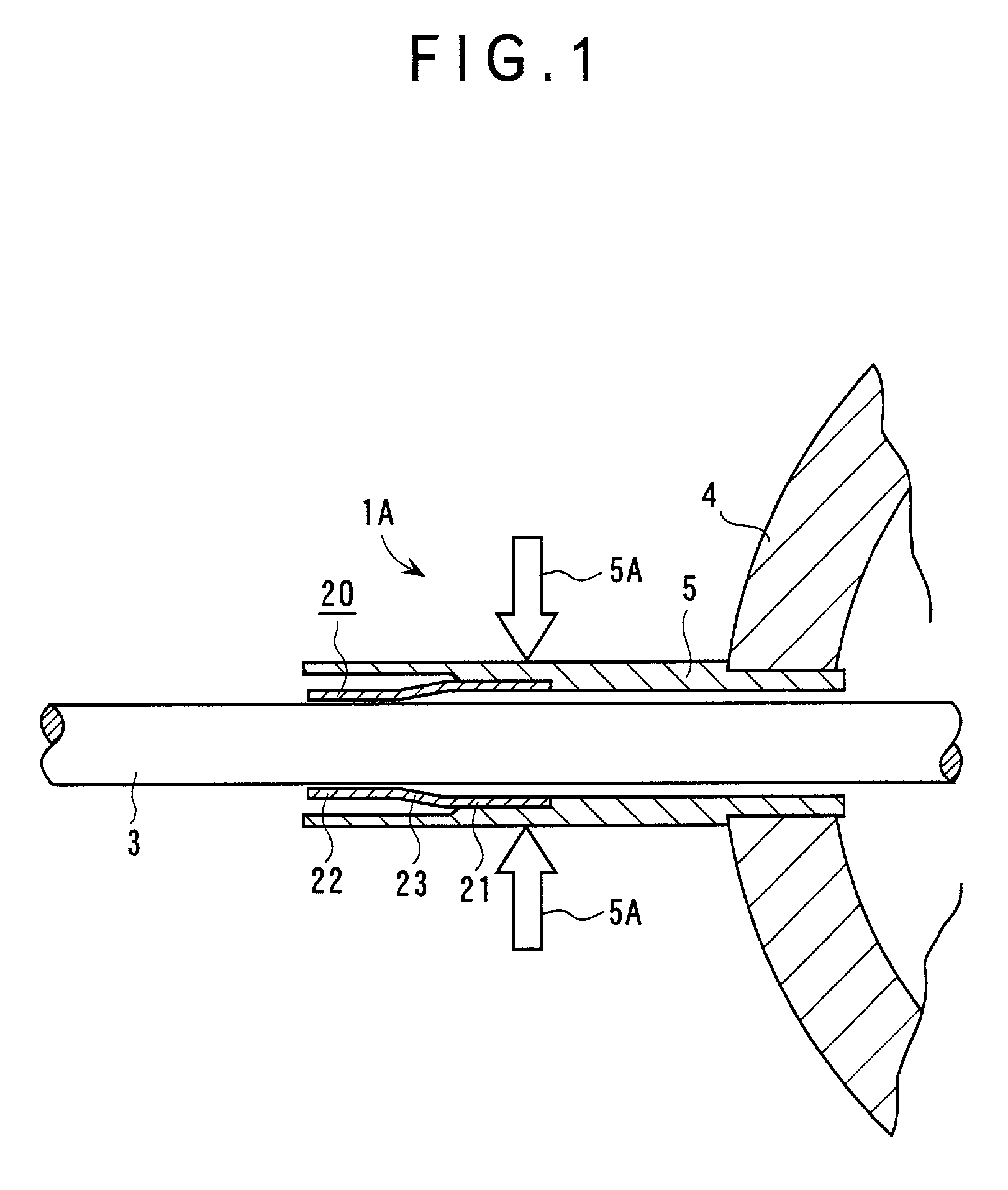
[0032] FIG. 1 shows a dial gauge 1A of the first embodiment of the present invention. As in the conventional dial gauge 1, the dial gauge 1A has a spindle 3 having a probe (not shown) to be in contact with the workpiece at a distal end thereof, a body 4 having a display (not shown) for displaying a measured value by a pointer, and a stem 5 provided to the body 4 for slidably holding the spindle 3 through a stem bush 20, where a dimension of the workpiece is measured by detecting a displacement of the spindle 3 relative to the body 4.
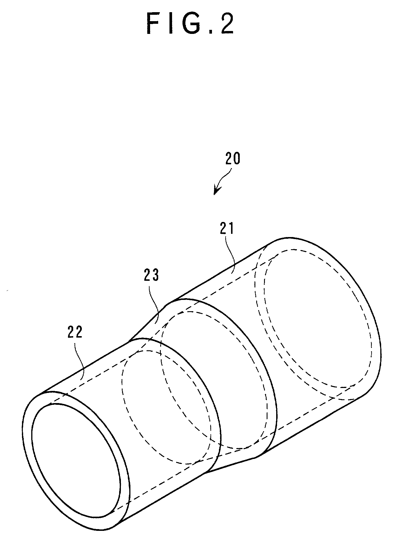
[0033] As shown in FIG. 2, the stem bush 20 has a fitting 21 fitted to an inner wall of the stem 5 and securing a predetermined clearance against the spindle 3, a holder 22 for slidably holding the spindle 3, the holder 22 securing a predetermined clearance against the inner wall of the stem 5, and an elastically deformable connector 23 for connecting the fitting 21 and the holder 22. The fitting 2l, the connector 23 and the holder 22 a...
second embodiment
[Second Embodiment]
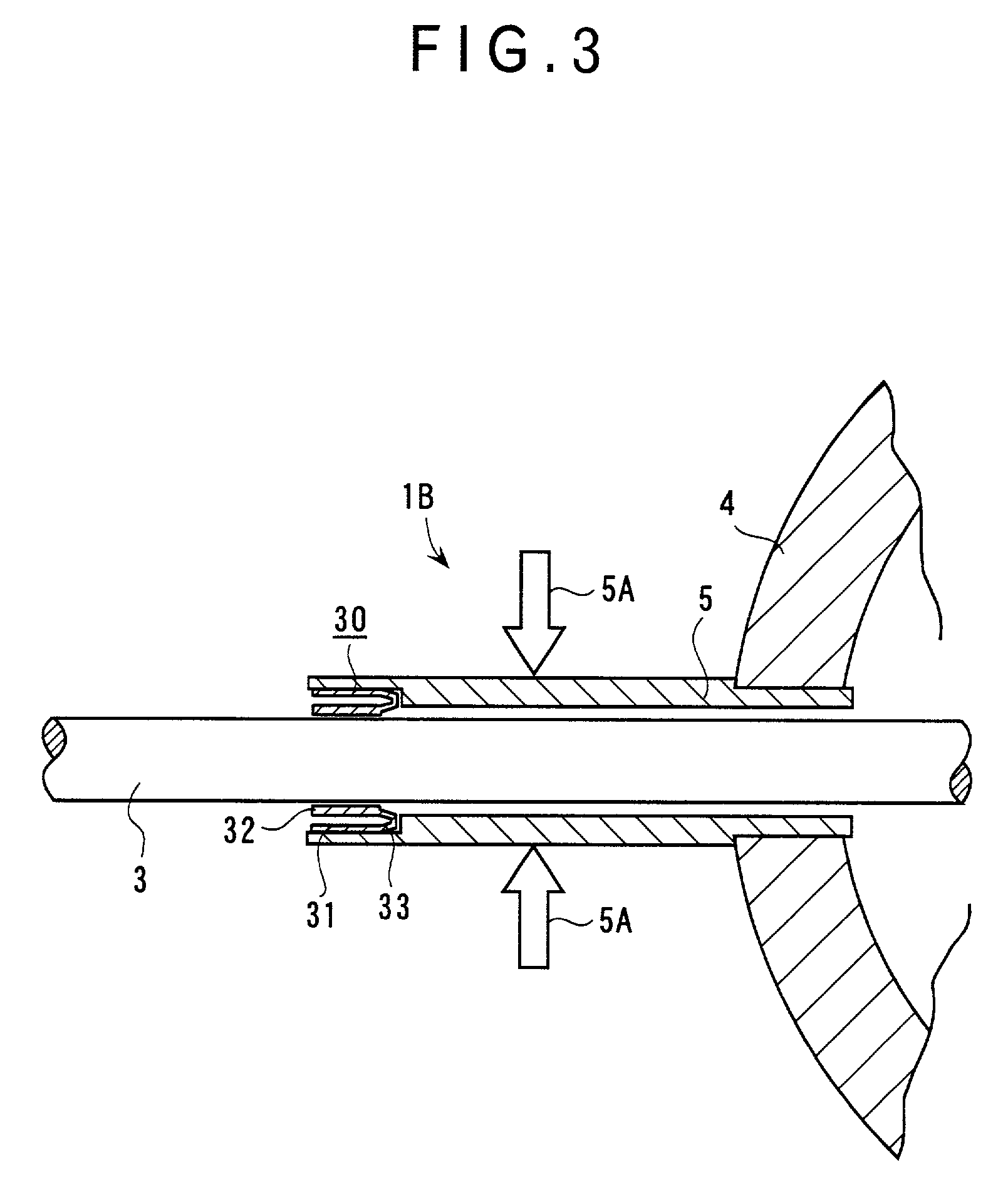
[0049] FIG. 3 shows a dial gauge 1B of the second embodiment of the present invention. Since the present embodiment differs from the above-described first embodiment only in the shape of the stem bush and the other arrangement and functions are the same, the same component will be applied with the same reference numeral to omit or simplify the description thereof.
[0050] As shown in FIG. 4, the stem bush 30 has a fitting 31 fixed to an inner wall of the stem 5 and having a predetermined clearance between the spindle 3, a holder 32 for slidably holding the spindle 3, the holder 32 securing a predetermined clearance against the inner wall of the stem 5, and an elastically deformable connector 33 for connecting the fitting 31 and the holder 32.
[0051] The fitting 31 is cylindrically formed with an outer circumference thereof fitted to the inner wall of the stem 5. The holder 32 is a cylinder having an inner diameter corresponding to the outer diameter of the spindle 3,...
third embodiment
[Third Embodiment]
[0055] FIG. 5 shows a dial gauge 1C of the third embodiment of the present invention. Since the present embodiment differs from the above-described first and second embodiments only in the shape of the stem bush and the other arrangement and functions are the same, the same component will be applied with the same reference numeral to omit or simplify the description thereof.
[0056] As shown in FIG. 6, the stem bush 40 has a fitting 41 fixed to an inner wall of the stem 5 and having a predetermined clearance against the spindle 3, a holder 42 for slidably holding the spindle 3, the holder 42 securing a predetermined clearance against the inner wall of the stem 5, and an elastically deformable connector 43 for connecting the fitting 41 and the holder 42. The fitting 41, the connector 43 and the holder 42 are sequentially arranged along the axial direction of the spindle 3.
[0057] The fitting 41 is cylindrically formed with an outer circumference thereof fixed to the in...
PUM
 Abstract
Description
Claims
Application Information
 - R&D
- Intellectual Property
- Life Sciences
- Materials
- Tech Scout
- Unparalleled Data Quality
- Higher Quality Content
- 60% Fewer Hallucinations
Browse by: Latest US Patents, China's latest patents, Technical Efficacy Thesaurus, Application Domain, Technology Topic, Popular Technical Reports.
© 2025 PatSnap. All rights reserved.Legal|Privacy policy|Modern Slavery Act Transparency Statement|Sitemap|About US| Contact US: help@patsnap.com


