Method and apparatus for data sampling

a data sampling and data technology, applied in pulse manipulation, pulse technique, instruments, etc., can solve the problem that the logic circuit cannot sample input data properly

Inactive Publication Date: 2002-08-01
LAPIS SEMICON CO LTD
View PDF0 Cites 5 Cited by
  • Summary
  • Abstract
  • Description
  • Claims
  • Application Information

AI Technical Summary

Benefits of technology

0004] Accordingly, an object of the present invention is to provide a data sampling circuit in which input data are sampled at appropriate timings to provide reliability of data sampling even if the input data are phase-shifted.

Problems solved by technology

According to the conventional logic LSI, if the input data is shifted in phase, the logic circuit could not sample the input data properly and mistakenly generates an unexpected output data.

Method used


Image

  • Method and apparatus for data sampling
  • Method and apparatus for data sampling
  • Method and apparatus for data sampling

Examples


Embodiment Construction

[0026] In the following detailed description of the preferred embodiments, reference is made to the accompanying drawings which form a part hereof, and in which is shown by way of illustration specific preferred embodiments in which the inventions may be practiced. These embodiments are described in sufficient detail to enable those skilled in the art to practice the invention, and it is to be understood that other embodiments may be utilized and that logical, mechanical and electrical changes may be made without departing from the spirit and scope of the present inventions. The following detailed description is, therefore, not to be taken in a limiting sense, and scope of the present inventions is defined only by the appended claims.

[0027] The invention is described in greater detail hereinafter relative to a non-limitative embodiment and with reference to the attached drawings, wherein show:

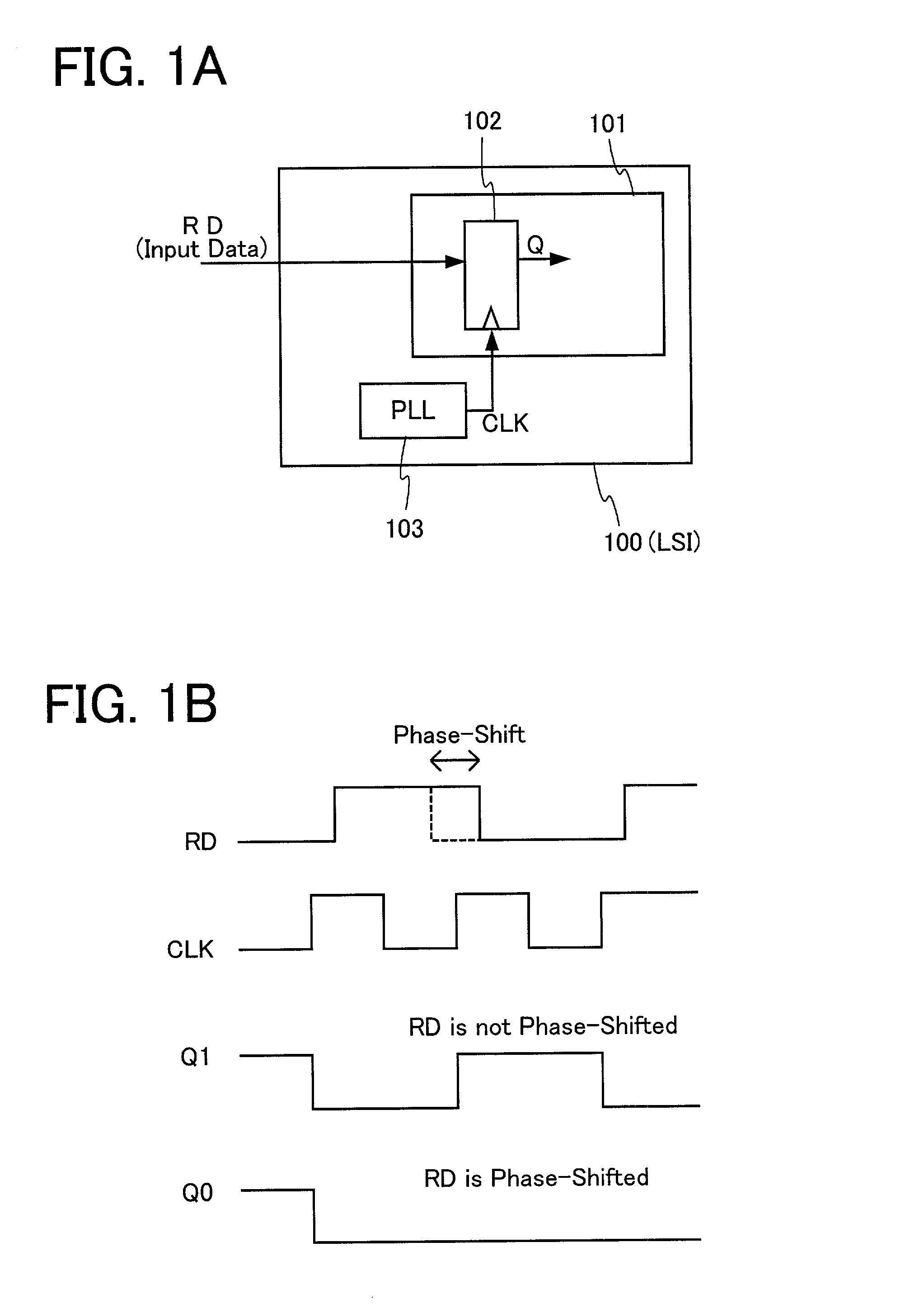
[0028] For better understanding of the present invention, a conventional technology is firs...


PUM


Abstract

A level-turning point of input data is detected; and a sampling clock is generated in response to the level-turning point of the input data. The input data are sampled in synchronization with the sampling clock.

Description

[0001] The present invention relates to a logic LSI in which input data are sampled in synchronization with a clock signal.[0002] A conventional logic LSI includes a logic circuit, a register and a PLL (Phase Locked Loop) circuit. The register is connected to a clock input terminal to an output terminal of the PLL circuit. The register receives input data and generates an output signal Q in synchronization with a clock signal generated in the PLL circuit to have a constant phase. In other words, the logic circuit samples the input data in synchronization with the constant clock signal.[0003] According to the conventional logic LSI, if the input data is shifted in phase, the logic circuit could not sample the input data properly and mistakenly generates an unexpected output data.OBJECTS OF THE INVENTION[0004] Accordingly, an object of the present invention is to provide a data sampling circuit in which input data are sampled at appropriate timings to provide reliability of data sampl...

Claims


Application Information

Patent Timeline
Patent Type & Authority Applications(United States)
IPC IPC(8): H04L7/033
CPCH04L7/0338
Inventor NATSUME, KENICHI
Owner LAPIS SEMICON CO LTD
Why Eureka
Try Eureka