Automatic door mechanism for projector

a projector and automatic technology, applied in the field of automatic door mechanism, can solve the problems of reducing operating efficiency, inconvenience in arranging components inside the casing, and poor environment of users, and achieve the effect of improving the discharge structure of driving heat, excellent radiation effect and performan

Inactive Publication Date: 2006-11-30
LG ELECTRONICS INC
View PDF15 Cites 5 Cited by
  • Summary
  • Abstract
  • Description
  • Claims
  • Application Information

AI Technical Summary

Benefits of technology

[0012] Accordingly, the present invention has been made to solve the aforementioned problems occurring in the discharge structure of the conventional beam projectors. More particularly, the present invention is disclosed to satisfy a demand on design and manufacturing of an effective discharge

Problems solved by technology

There is a disadvantage in this type of air discharge structure according to the conventional method as described in that an increase of the driving time of a beam projector causes a temperature rise in ambient air of an interior space such that a periodical ventilation is needed which decreases the operating efficiency and simultaneous

Method used


Image

  • Automatic door mechanism for projector
  • Automatic door mechanism for projector
  • Automatic door mechanism for projector

Examples


Embodiment Construction

[0027] Reference will now be made in detail to the embodiments of the present invention, examples of which are illustrated in the accompanying drawings.

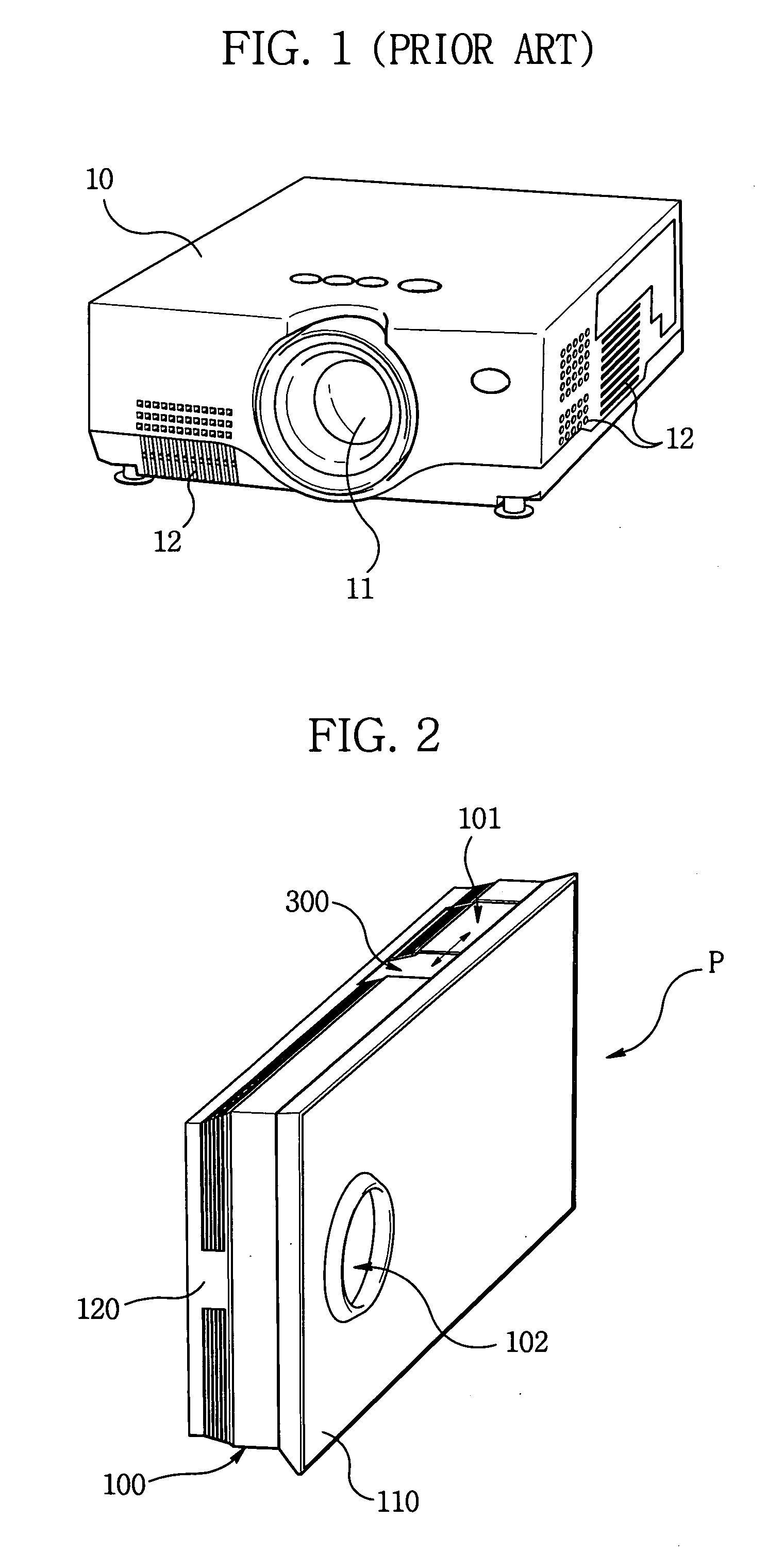
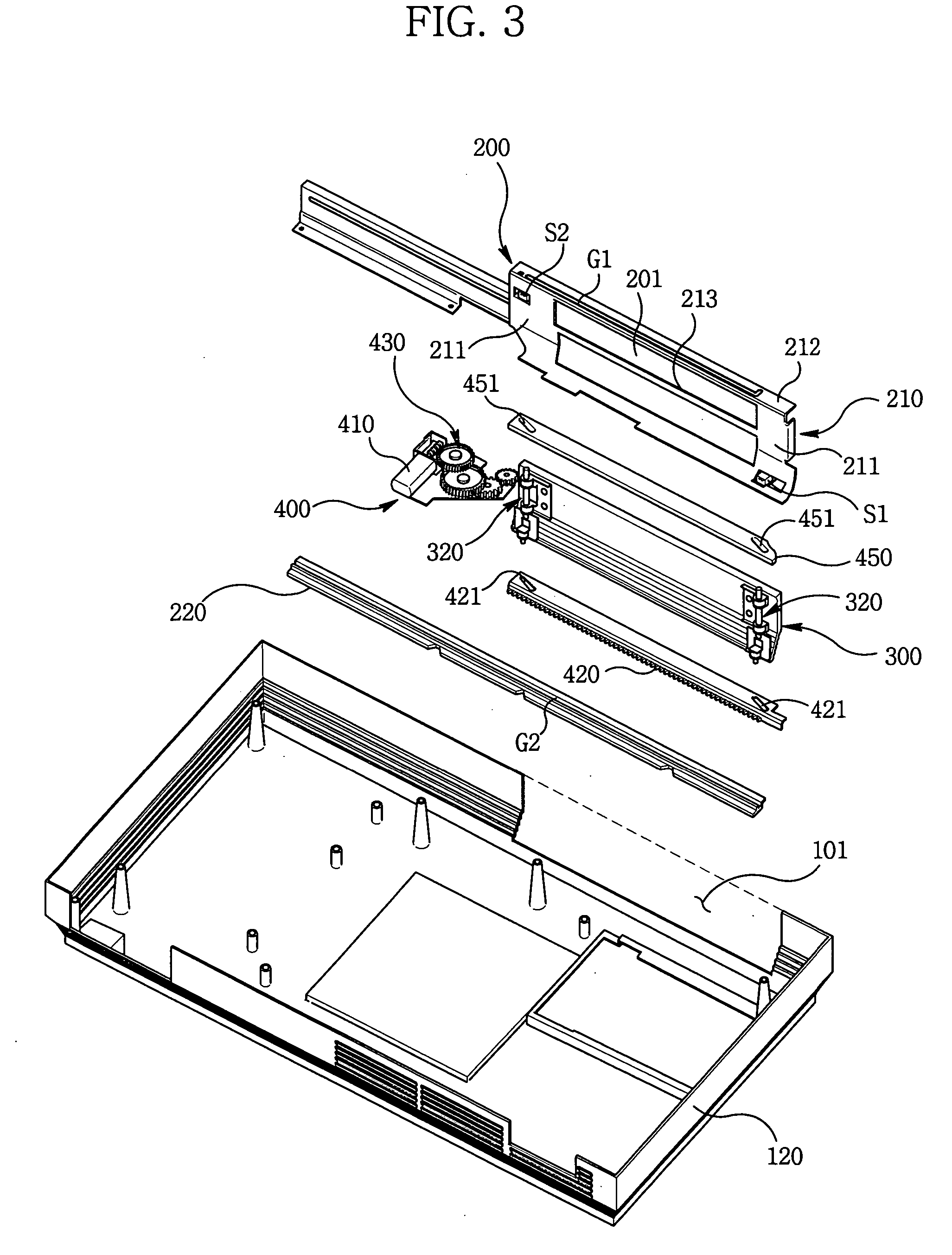
[0028]FIG. 2 is a schematic external perspective view illustrating a slim type beam projector adopted with an automatic door mechanism according to an embodiment of the present invention. An case 100 has a framed panel style external structure formed by a front case 110 and a rear case 120, each separately manufactured and coupled therebetween, such that it has a slim-down style to be used for wall hanging or stand-up purpose as in, for example, flat panel LCD (Liquid Crystal Display) TVs or Plasma Display Panels (PDPs).

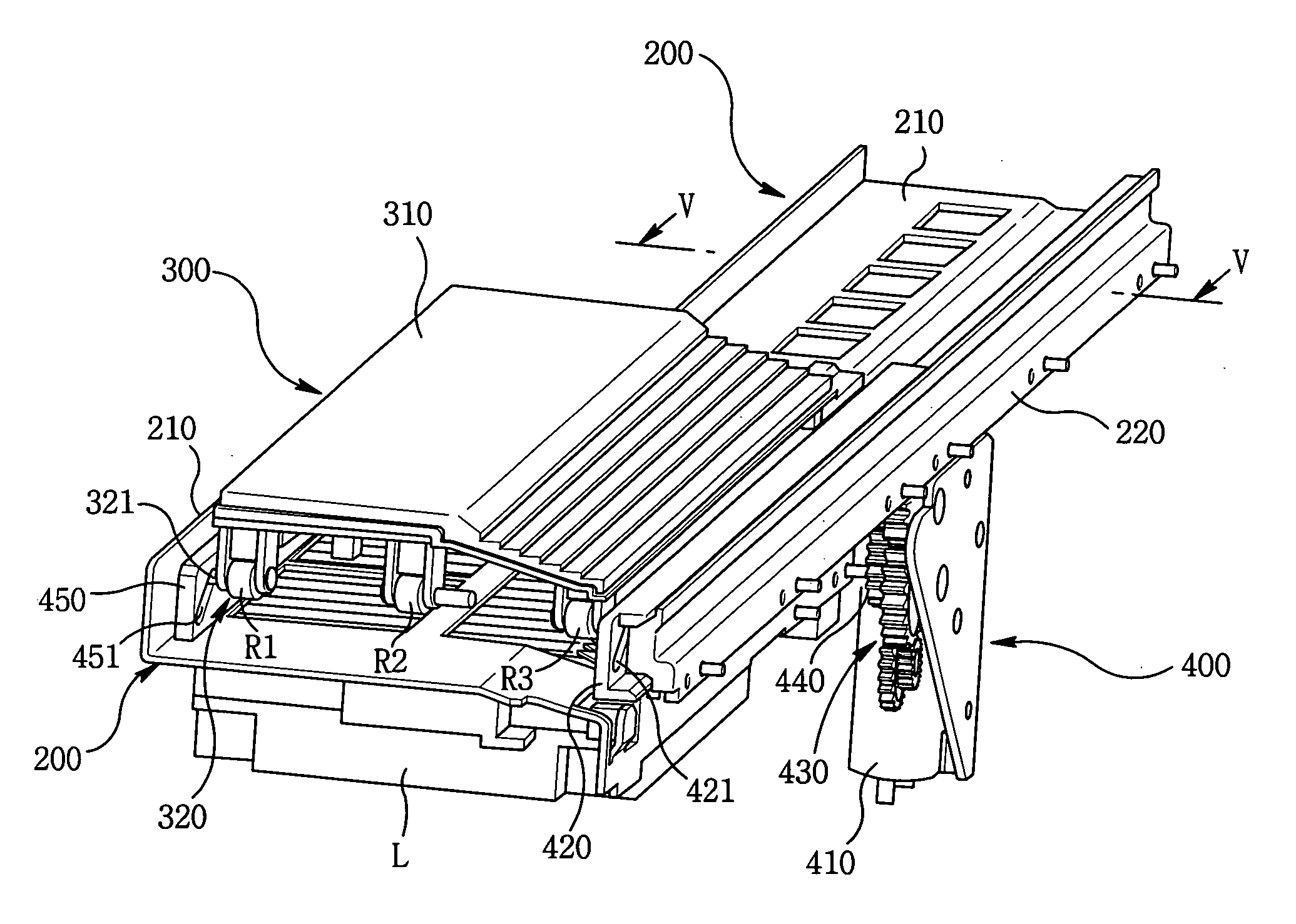
[0029] In the illustrated embodiment, a discharge unit 101 is located close to the top side of the case 100. The heat generated in the projector is induced upwardly and discharged through the heat discharging opening at the top side of the case 100. A discharge door assembly 300 is provide to operate in cooperation ...


PUM


Abstract

An automatic door apparatus of a projector is provided. The projector includes a case. The case has a heat discharging opening for discharging heat out of the projector. The automatic door apparatus includes: a frame disposed at the case, the frame facing the heat discharge opening; a door assembly reciprocally movable along the frame in a first direction for opening and closing the heat discharge opening; and a driving unit disposed in the case for moving the door assembly along the first direction, the driving unit moving the door assembly along the first direction from a first position to a second position to open the heat discharge opening in response to a first operation mode of the projector, the driving unit moving the door assembly along the first direction from the second position to the first position to close the heat discharge opening in response to a second operation mode of the projector.

Description

CROSS-REFERENCE TO RELATED APPLICATION [0001] This Nonprovisional Application claims priority under 35 U.S.C. §119(a) on Patent Application No. 10-2005-0043428 filed in Korea on May 24, 2005, the entire contents of which are hereby incorporated by reference. BACKGROUND OF THE INVENTION [0002] 1. Field of the Invention [0003] The present invention relates to an opening / closing apparatus for a small door mounted at an electrical / electronic apparatus, and more particularly to an exhaust door opening / closing apparatus for facilitating discharging heat out of a projector. Specifically, the present invention relates to an automatic door mechanism for a slim type wall-hanging or stand-up beam projector. [0004] 2. Description of the Related Art [0005] Recently, distribution of projectors capable of obtaining image information via a large screen is suddenly increased in order to satisfy demands of consumers as broadcasting via high definition televisions are thriving and markets of home thea...

Claims


Application Information

Patent Timeline
IPC IPC(8): G03B21/16
CPCG03B21/16H04N9/3144H04N9/3141H04N5/74
Inventor YOO, SEUNG-HON
Owner LG ELECTRONICS INC
Why Eureka
Try Eureka