Intermediate- and low-level radioactive waste treatment method

A low-radioactivity and waste treatment technology, applied in radioactive purification, nuclear engineering, etc., can solve the problem of occupying large nuclear waste yard space, achieve good economic benefits, eliminate nuclear radiation pollution and atmospheric environmental pollution, and have reliable principles

Active Publication Date: 2017-05-31
青岛天和清原科技有限公司
View PDF7 Cites 5 Cited by
  • Summary
  • Abstract
  • Description
  • Claims
  • Application Information

AI Technical Summary

Problems solved by technology

Due to the low hazard of medium and low radioactive waste, the international practice is to dig trenches about 10-20 meters deep on the ground, and then build various anti-radiation engineering barriers, and put the radioactive waste that has been incinerated, compressed and solidified into tanks. After a period of time, the radioactive substances in these wastes will decay into harmless substances. This method has been developed for decades. Although the technology is very mature, it requires a large amount of nuclear waste. Yard space

Method used


Image

  • Intermediate- and low-level radioactive waste treatment method
  • Intermediate- and low-level radioactive waste treatment method
  • Intermediate- and low-level radioactive waste treatment method

Examples


Embodiment 1

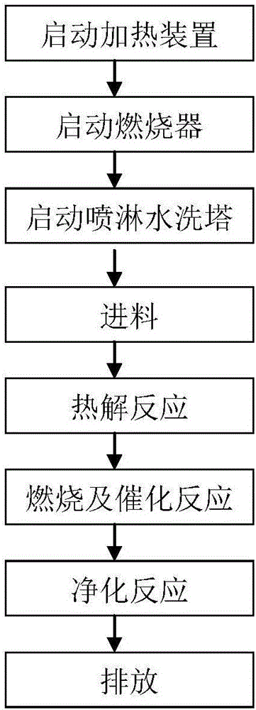
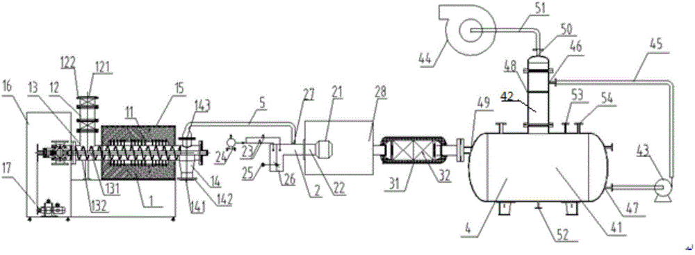
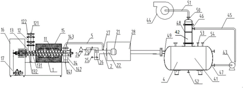
[0033] The specific process steps of the medium and low radioactive waste treatment method involved in this embodiment are:

[0034] (1) Start the heating device 11: start the heating device 11 of the pyrolysis reactor 1, and set the temperature of the first temperature controller 16 to be 300-600° C.;

[0035] (2) Start the burner 2: start the automatic fuel circuit oil pump 24, open the two-stage solenoid valve 23 to automatically ignite and burn sequentially, when the fuel part of the burner burns stably, keep the temperature of the combustion chamber 28 at 800-1300°C, pyrolysis The gas enters the burner 2 for combustion, that is, the burner 2 is sprayed and atomized by the middle part, and the automatic fuel circuit oil pump 24 is used to adjust the amount of fuel, and the servo motor 25 adjusts the air inlet 26 to ensure that the pyrolysis gas is fully burned;

[0036] (3) Start the spray water washing tower 3: start the circulating water pump 43 and the induced draft fan...

Embodiment 2

[0047] The difference between this embodiment and Embodiment 1 is that in step (4), the step of adding solid catalyst 32 is omitted, and medium and low radioactive waste is sent into the closed feed system 12 through the feed port 121, and the sealed feed valve 122 is closed; The difference between the device used in the medium and low radioactive waste treatment method involved in the embodiment and the device used in embodiment 1 is that the structure of the catalytic converter 3 is omitted, and the output end of the burner 2 is washed with the spray water through the high temperature resistant pipeline 5 The second gas inlet 49 of the tower 4 is connected.

Embodiment 3

[0049]The difference between this embodiment and Embodiment 1 lies in step (2), before starting the burner 2, open the control valve 61 of the exhaust gas outlet of the burner 2, realize heat exchange between the exhaust gas of the burner 2 and the inlet gas, and increase the temperature of the inlet gas of the burner 2 , to realize heat recycling and reduce energy consumption; the difference between the device used in the low-medium radioactive waste treatment method involved in this embodiment and the device used in Embodiment 1 is to increase the heat exchanger 6 structure, and the heat exchanger 6 is A high temperature resistant pipeline 62 with a control valve 61, the input end of the heat exchanger 6 communicates with the exhaust gas outlet of the burner 2, the output end of the heat exchanger 6 communicates with the catalytic converter 3, and the high temperature resistant pipeline 62 of the heat exchanger 6 It is spirally arranged on the outside of the gas inlet pipelin...


PUM


Abstract

The invention belongs to the technical field of intermediate- and low-level radioactive waste treatment and relates to an intermediate- and low-level radioactive waste treatment method. The intermediate- and low-level radioactive waste treatment method is achieved in an intermediate- and low-level radioactive waste treatment device and is used for treating organic combustible waste which contains radioactive substances and is generated by hospitals, factories, research institutions and nuclear power plants. The sludge volume reduction and the harmless treatment of the intermediate- and low-level radioactive waste are achieved. The sludge volume reduction rate is more than 95%. The difficulties of big deposit volume and difficult storage of the intermediate- and low-level radioactive waste are solved. Firstly, heating equipment is started, then a burner is started, then a spray water scrubber is started to carry out pre-treatment, then feedstock is carried out, the waste is pyrolyzed, burned, and experiences catalytic reaction, and finally, is purified and discharged. The process is simple in method, reliable in principle, high in sludge volume reduction rate, good in curing effect, environmentally friendly in application, low in investment and operation costs, energy-saving and environmentally friendly, and has a good economic benefit and a wide market prospect.

Description

[0001] Technical field: [0002] The invention belongs to the technical field of low and medium radioactive waste treatment, and relates to a treatment method for low and medium radioactive waste, which is implemented in a treatment device for low and medium radioactive waste, and is used to treat organic combustible materials containing radioactive substances produced by hospitals, factories, research institutions and nuclear power plants. Class waste, achieve volume reduction and harmless treatment of medium and low radioactive waste, with a volume reduction rate of more than 95%. [0003] Background technique: [0004] From the technical level, radioactive waste is mainly divided into two categories: high radioactivity and low and medium radioactivity. High-level radioactive waste mainly includes spent fuel and its disposal products produced by nuclear fuel after power generation; medium and low-level radioactive waste generally includes nuclear power plant polluting equipme...

Claims


Application Information

Patent Timeline
Patent Type & Authority Applications(China)
IPC IPC(8): G21F9/14G21F9/32G21F9/06G21F9/30
CPCG21F9/06G21F9/14G21F9/30G21F9/32
Inventor 杨成赵小鋆张伟孙强管颖
Owner 青岛天和清原科技有限公司
Why Eureka
Try Eureka