Base station search method and mobile terminal apparatus

US20020154609A1Active Publication Date: 2002-10-24GK BRIDGE 1
10 Cites 17 Cited by

Patent Information

Authority / Receiving Office
US · United States
Current Assignee / Owner
Publication Date
2002-10-24

Smart Images

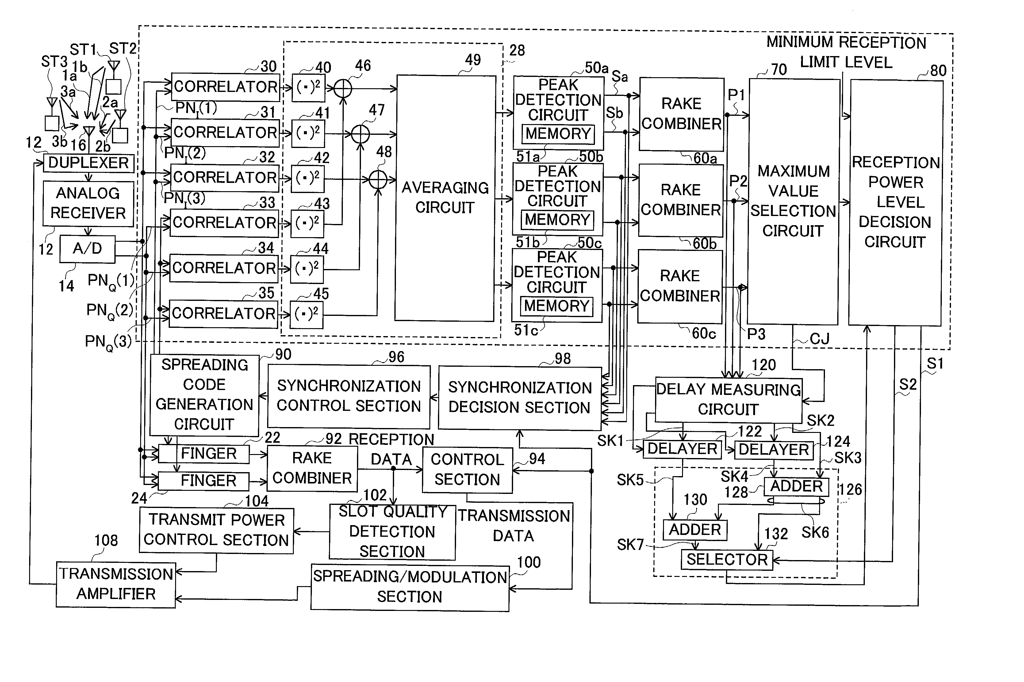
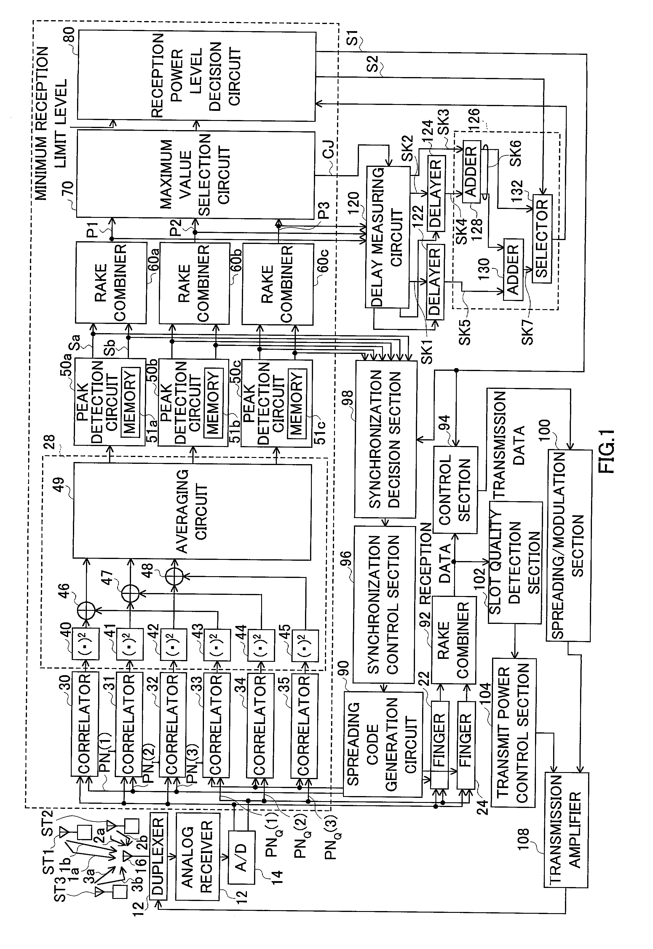
  • Figure 1
    Figure 1
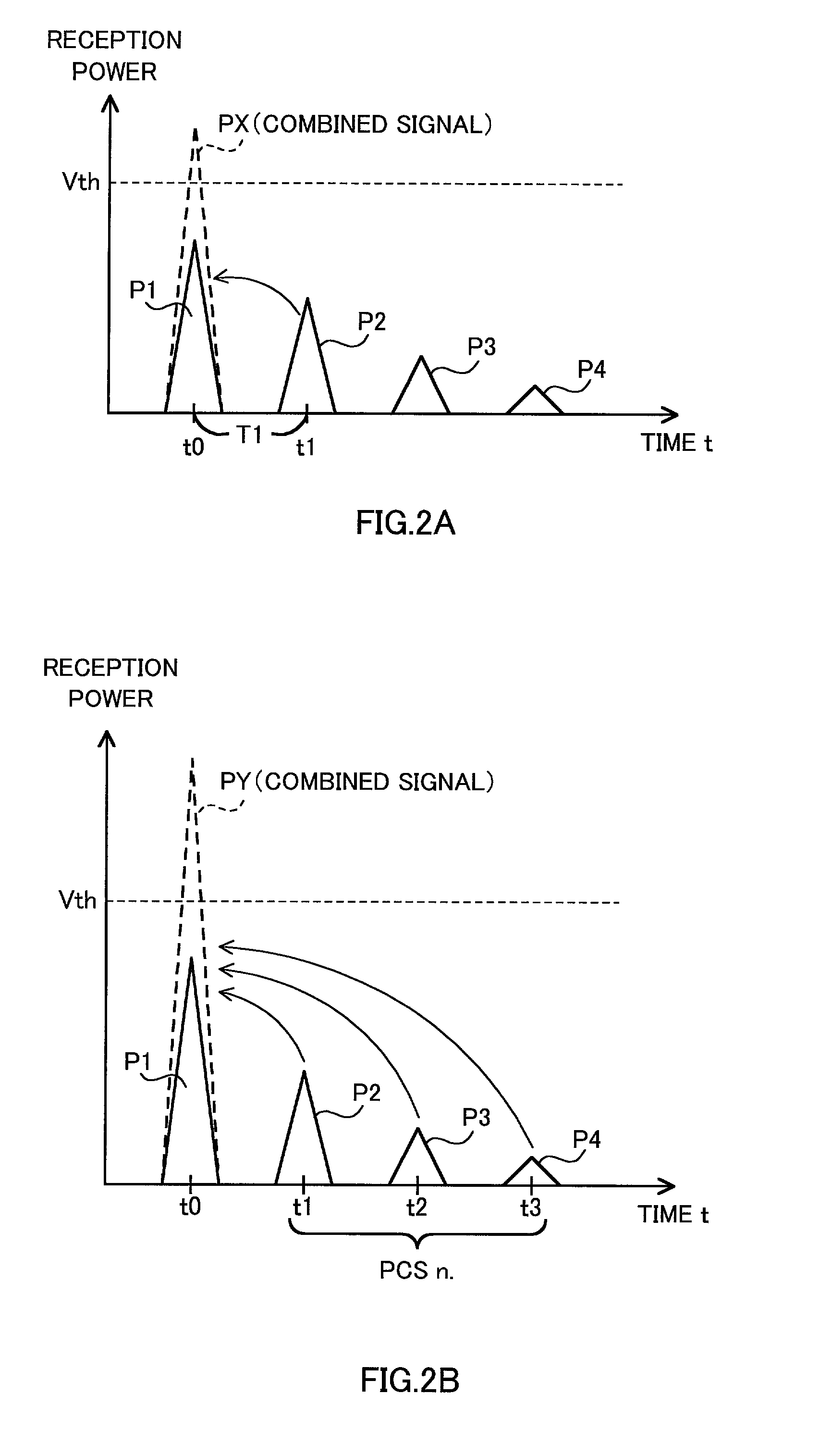
  • Figure 2
    Figure 2
  • Figure 3
    Figure 3
Patent Text Reader

Abstract

The present invention uses site diversity reception and RAKE combining reception for the method for a CDMA communication mobile terminal to carry out a cell search to search for a base station with which to communicate. Even if the reception power levels of synchronization acquisition signals sent from a plurality of base stations are lower than a predetermined threshold, in the case where the power level of a signal combining those signals is equal to or greater than the predetermined threshold, the mobile terminal continues processing of requesting position registration to any one of the plurality of base stations and thereby improves communicability.
Need to check novelty before this filing date? Find Prior Art

Description

[0001] 1. Field of the Invention

[0002] The present invention relates to a base station search method and mobile terminal apparatus in a CDMA-based mobile communication.

[0003] 2. Description of the Related Art

[0004] A CDMA-based mobile communication system includes a plurality of base stations in a service area and a mobile station transmits / receives signals to / from a nearest base station.

[0005] A radio zone covered by one base station is called a "cell (or sector)".

[0006] When power is turned on, a mobile station searches for a nearest base station, then transmits / receives predetermined information to / from the searched base station and finally enters into a communication ready state (ready for receiving a call signal from the base station: standby state).

[0007] A CDMA system is broadly divided into W-CDMA system (European-Japanese system) and cdma2000 (IS-95 system: USA system).

[0008] According to the first system, each base station operates asynchronously. On the other hand, the se...

Examples

embodiment 2

[0160] Of the configuration shown in FIG. 1, this embodiment will describe specific examples of circuit configurations of the delay measuring circuit, delay circuit and reception power level decision circuit.

[0161] FIG. 5 is a circuit diagram showing specific configurations of delay measuring circuit 120, delay circuit 122 or 124.

[0162] As shown in the figure, delay measuring circuit 120 is constructed of distributor 150, counter start circuit (D type flip flop) 152, counter stop circuit (D type flip flop) 154 and counter circuit 156.

[0163] Distributor 150 selects a received signal with a maximum power level out of received signals P1 to P3 based on information indicating the result of a comparison of the power levels of received signals P1, P2 and P3 from the respective base stations and outputs from output terminal a.

[0164] Furthermore, the received signal with the next highest power level (this is the received signal to be added) is output from output terminal b.

[0165] Counter 15...