

Wireless Diversity Reception Apparatus and Reception Method
a technology of diversity and reception apparatus, which is applied in the direction of power management, transmission monitoring, sustainable buildings, etc., can solve the problems of inability to accurately control the power of the mobile station apparatus, the mtbf (mean time between failure) may degrade, and the inability to accurately perform the power control of the mobile station. the effect of mobile station transmission
- Summary
- Abstract
- Description
- Claims
- Application Information
AI Technical Summary
Benefits of technology
Problems solved by technology
Method used
Image

Examples
first exemplary embodiment
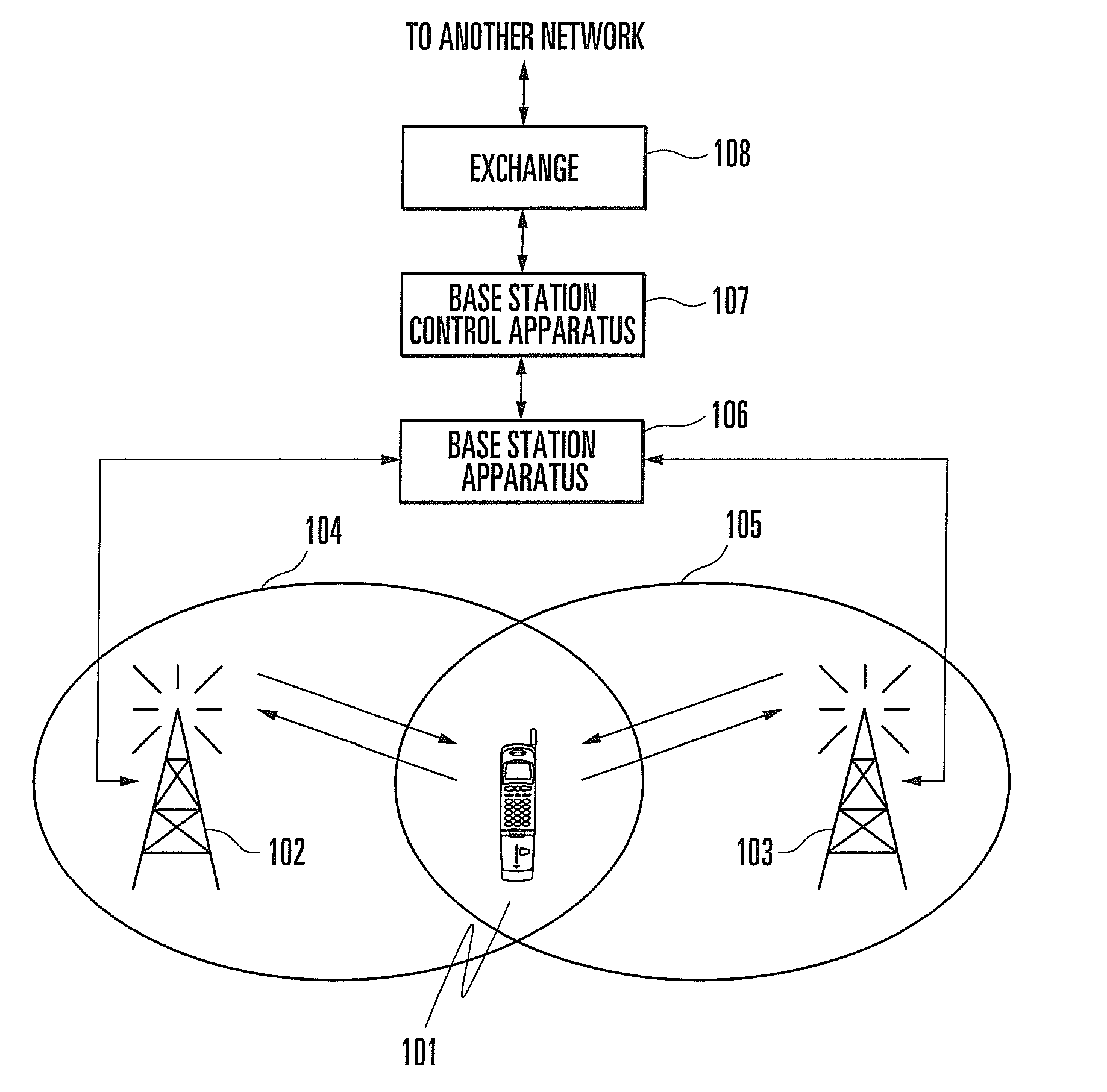
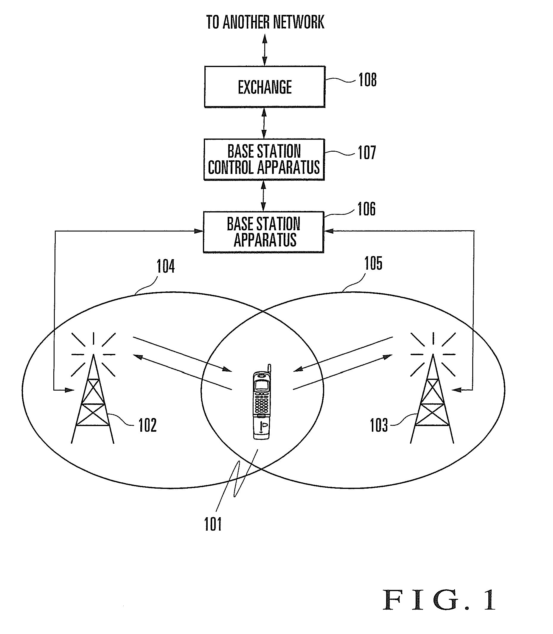
[0026]FIG. 1 shows the arrangement of a mobile communication system including a base station apparatus according to the first exemplary embodiment of the present invention. A mobile station 101 is a wireless communication terminal such as a portable phone. Antennas 102 and 103 are two antenna systems installed in one cell corresponding to the communication range of a single base station apparatus 106. Areas 104 and 105 are radio areas covered by the antennas 102 and 103, respectively.
[0027]Referring to FIG. 1, the mobile station 101 is located in the overlap area of the areas 104 and 105. Each of the mobile station 101 and the base station apparatus 106 transmits power control information to the counter device and controls the transmission power of the counter device based on the result of comparison between the target reception quality and the actual reception quality. The counter device of the mobile station 101 is the base station apparatus 106. The counter device of the base sta...
second exemplary embodiment
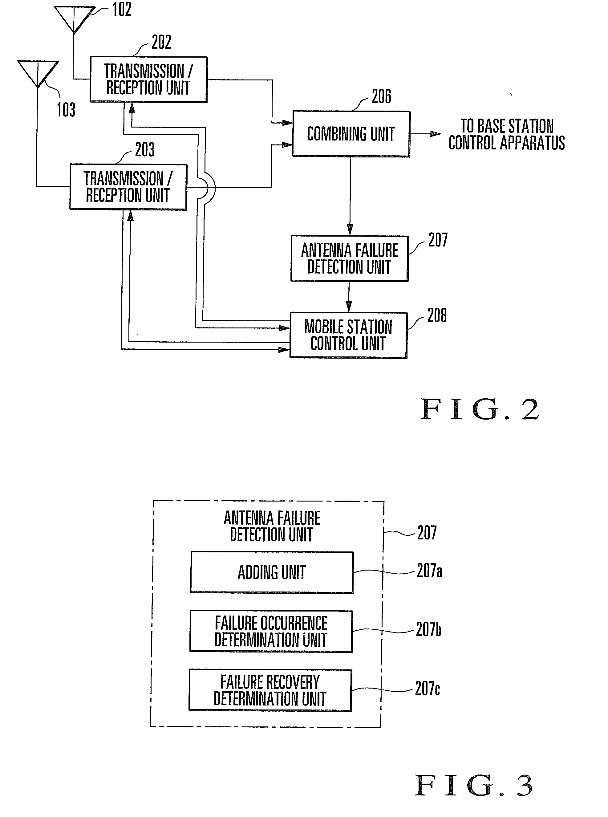
[0065]The second exemplary embodiment of the present invention will be described. FIG. 7 shows the arrangement of a base station apparatus according to the second exemplary embodiment of the present invention. The same reference numerals as in FIG. 2 denote the same parts in FIG. 7. In this exemplary embodiment, the first exemplary embodiment will be explained in more detail. The base station apparatus includes transmission / reception units 202 and 203, demodulation units 204 and 205, combining unit 206, antenna failure detection unit 207, and mobile station control unit 208.
[0066]The demodulation units 204 and 205 demodulate baseband signals converted by the transmission / reception units 202 and 203, respectively, and output the demodulated signals to the combining unit 206.
[0067]The combining unit 206 combines the signals output from the demodulation units 204 and 205 and outputs the signal of the combining result to a base station control apparatus 107. The combining unit 206 also ...
third exemplary embodiment
[0068]The third exemplary embodiment of the present invention will be described. FIG. 8 shows the arrangement of a base station apparatus according to the third exemplary embodiment of the present invention. The same reference numerals as in FIG. 2 denote the same parts in FIG. 8. A combining unit 306 and an antenna failure detection unit 307 of this exemplary embodiment are formed by adding some functions to the combining unit 206 and the antenna failure detection unit 207 of the first exemplary embodiment.
[0069]The antenna failure detection unit 307 sends antenna failure information to the combining unit 306 as well.
[0070]Upon recognizing based on updated antenna failure information that an antenna failure has occurred, the combining unit 306 excludes the reception signal of the antenna with the failure from selection of antenna reception signals to be used for RAKE combining.
[0071]If the reception signal of the antenna with the failure is included in the targets of RAKE combining...
PUM
 Abstract
Description
Claims
Application Information