Joining system and method for floor boards and boards therefor

a technology of floor boards and joints, applied in the direction of load-supporting elements, structural elements, building components, etc., can solve the problems of one person controlling both ends simultaneously, not always easy to join the boards, and especially difficult to achieve the effect of jointing

Inactive Publication Date: 2003-01-16
SODERBERG JAN
View PDF0 Cites 315 Cited by
  • Summary
  • Abstract
  • Description
  • Claims
  • Application Information

AI Technical Summary

Problems solved by technology

However, it is not always easy to join the boards, as the entire length of a protrusion on a board has to be fitted into the recess of an existing, already laid-down board, before the new board can be pivoted and locked into its final position.
This is especially difficult if the board is warped and not entirely straight, and too long for one person to control both ends simultaneously.

Method used


Image

  • Joining system and method for floor boards and boards therefor
  • Joining system and method for floor boards and boards therefor
  • Joining system and method for floor boards and boards therefor

Examples


second embodiment

[0045] In FIGS. 7 to 10 a second embodiment is shown. Corresponding parts are denoted by the same reference numerals as in FIGS. 1 to 6 with the FIG. 2 added in front. In this embodiment the shape of the top of the hooks 21 and the corresponding downwardly facing inside of the edge 23 have a different design. Instead of being straight and angled the sides are configured with horizontal surfaces so that the hook 21 has a flat top 25 and the inner side a correspondingly flat abutment surface 26. If the boards should move relative each other horizontally, they will be guided by both the top flat contact surface at 25 and 26, and by the lower flat contact surface at the lower side of the hook 21 and the corresponding upwardly facing inner side of the edge 23. The guiding results in that there will be no difference in height beween the upper surfaces of the boards if the hook 21 should move relative the recess 211.

[0046] The shoulder 27 is shown straight in the figures but may also have ...

first embodiment

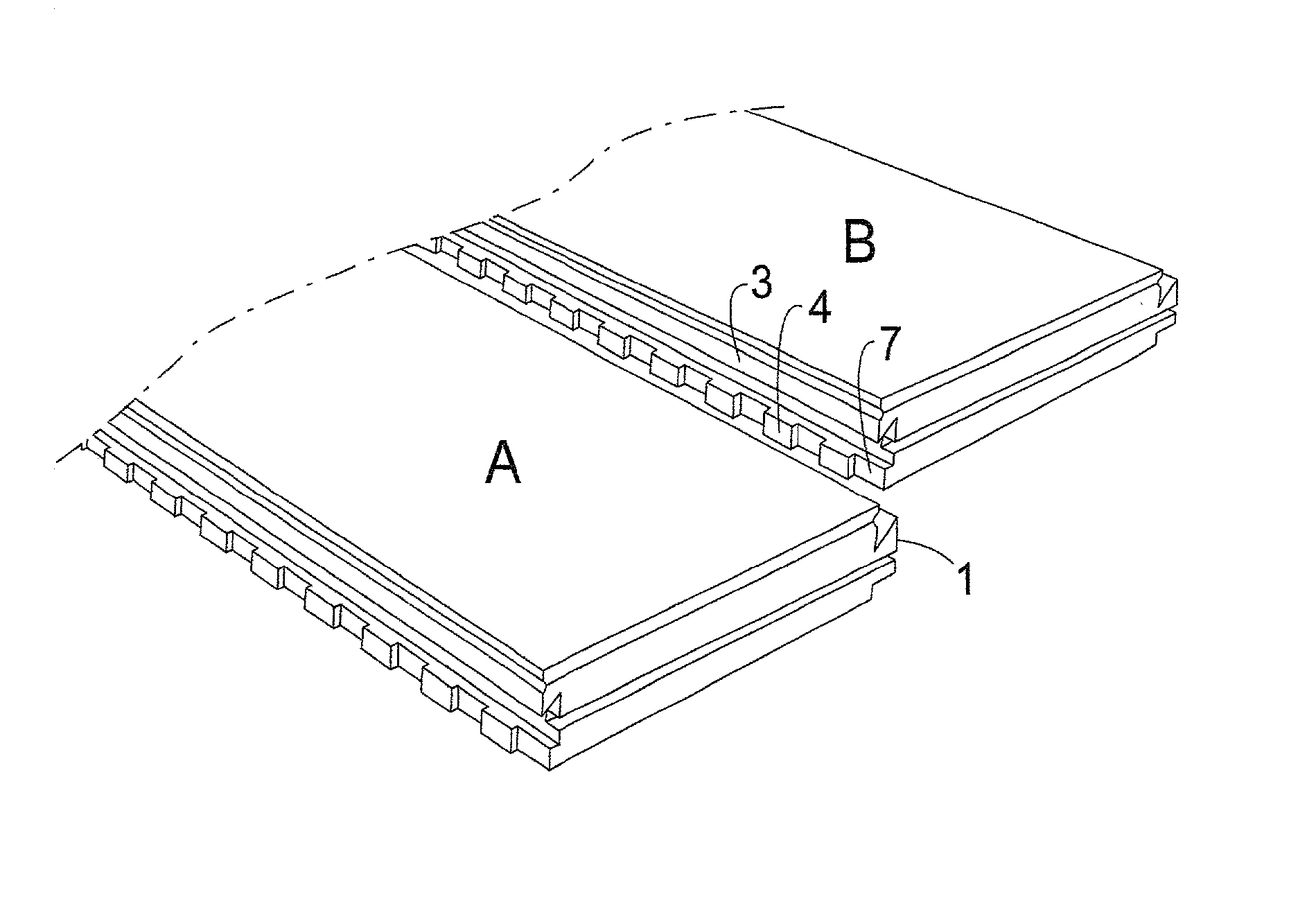
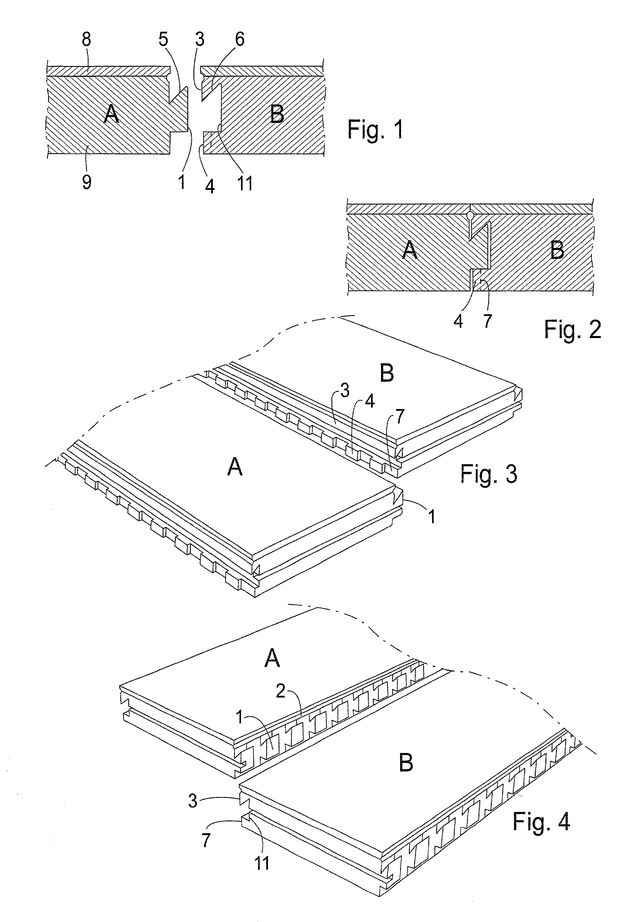
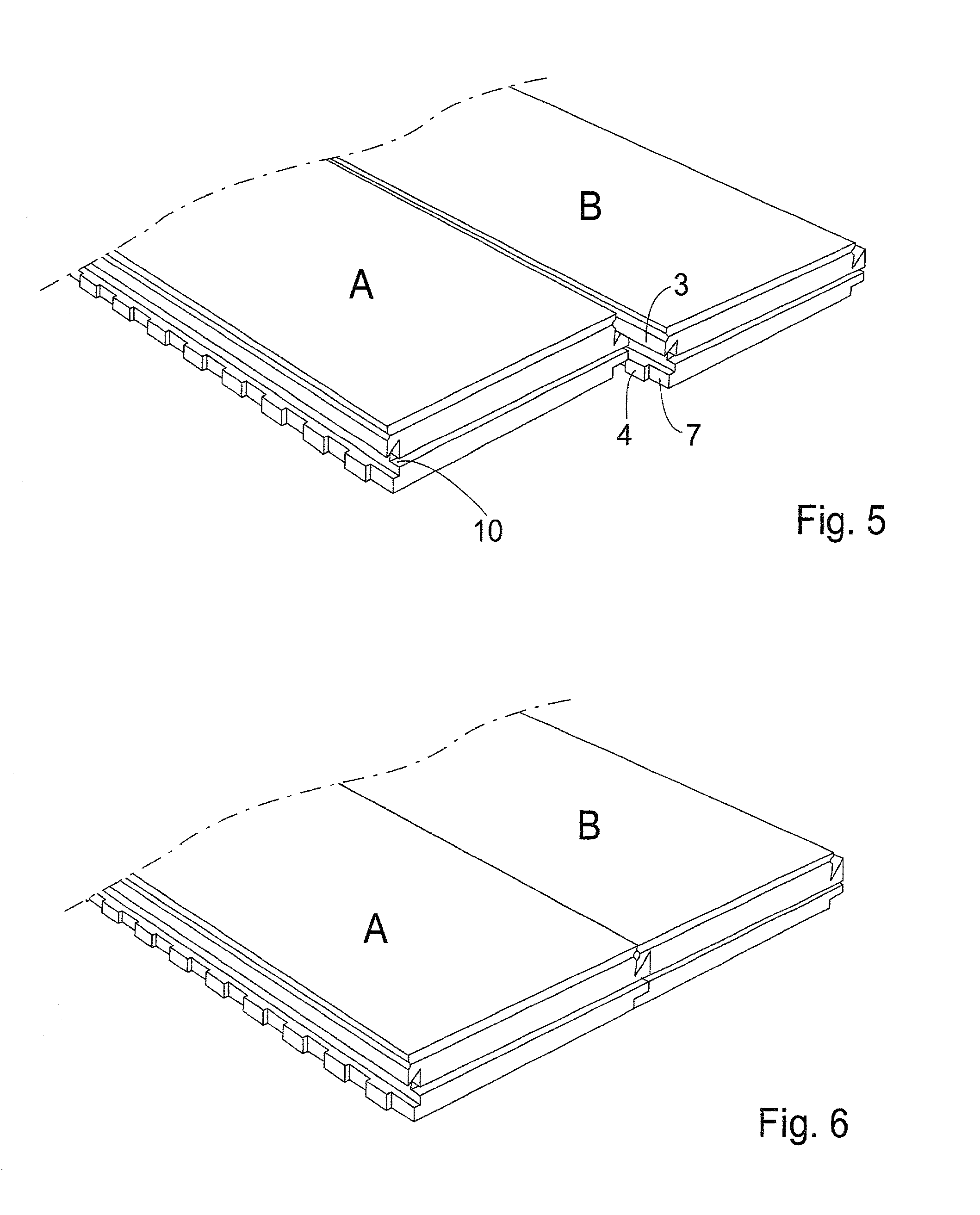
[0064] The short sides of the boards of all the embodiments may be provided with conventional groove-and-tenon joints (or another well known system). This is illustrated in connection with the first embodiment in FIGS. 3, 4, 5 and 6 by a groove 10. The corresponding tenon is located at the other short end and thus is not visible.


PUM


Abstract

The invention relates to a joining system and method for floorboards, e.g. for parquetry. The joining system comprises floor boards intended to be joined with each other, wherein a first board (A) has a protrusion fitting into a recess in a second board (B). The protrusion on the first board comprises hooks (1) with intermediate slots (2) or chamfers. The recess (11) in the second board (B) is delimited on the top side by a solid edge (3), and on the bottom side by an edge having heads (4) dimensioned to be inserted through the slots (2) of the first board (A). The invention will replace the traditional groove and tenon technique. By providing slots or chamfers in the protrusion corresponding to the tenon, and corresponding cuts in the lower limiting edge of the groove, the boards can be joined in a substantially vertical or transversal movement and then be locked by a horizontal movement in the longitudinal direction of the boards. At the same time, the protrusion is shaped like hooks engaging the groove. Hereby, the joining will be very simple to perform, whilst at the same time providing a strong joint.

Description

[0001] The present invention relates to a joining system and method for floorboards, panels and sheaves, but foremost for parquetry. The invention will replace the traditional groove and tenon technique. By providing slots or chamfers in the protrusion corresponding to the tenon, and corresponding cuts in the lower limiting edge of the groove, the boards can be joined in a substantially vertical or transversal movement and then be locked by a horizontal movement in the longitudinal direction of the boards. At the same time, the protrusion is hook-shaped so that the protrusion engages the groove. Through this, the joining will be very simple to perform, whilst at the same time providing a strong joint.STATE OF THE ART[0002] The traditional groove and tenon technique for floorboards has been known in the art for a long time. Furthermore, there are a number of alternative technical solutions available with various shapes of protrusions and recesses. Through giving the protrusions vario...

Claims


Application Information

Patent Timeline
Patent Type & Authority Applications(United States)
IPC IPC(8): E04F15/02E04F15/04
CPCE04F15/02E04F15/04E04F2201/0123E04F2201/022E04F2201/07
Inventor PALMBERG, ULF
Owner SODERBERG JAN
Why Eureka
Try Eureka