Air pressure gauge assembly for continuous monitoring of tire inflation pressure

a technology of air pressure gauges and assembly parts, which is applied in the direction of instruments, tyre measurements, vehicle components, etc., can solve the problems of tire failure, tire wear excessive, and loss of fuel economy

Inactive Publication Date: 2003-12-11
TIRO TECH
View PDF6 Cites 8 Cited by
  • Summary
  • Abstract
  • Description
  • Claims
  • Application Information

AI Technical Summary

Problems solved by technology

Under inflation of a tire can cause excessive wear of the tire, tire failure, loss of fuel economy, excessive engine drag, increased emissions, and depletion of fossil fuels.
This can cause a problem when replacing the tire and...

Method used


Image

  • Air pressure gauge assembly for continuous monitoring of tire inflation pressure
  • Air pressure gauge assembly for continuous monitoring of tire inflation pressure
  • Air pressure gauge assembly for continuous monitoring of tire inflation pressure

Examples


embodiment 50

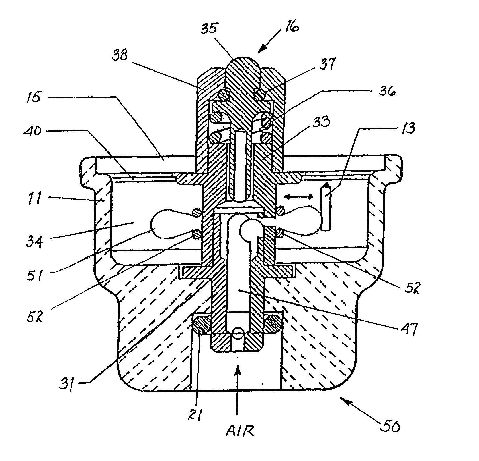
[0052] Turning now to FIG. 5a, a cross sectional view of a third preferred embodiment 50 of the valve stem mountable, flow-through air pressure gauge assembly 10 is shown. In the second air pressure gauge assembly 50 the sensing element 12 (shown in FIG. 1) comprises a diaphragm 51, preferably having a doughnut-shape. The diaphragm 51 has a sealed connection to the inner chamber 47 of the sensing element housing 31. By mounting the gauge body 11 to the valve stem 20, the lower end of the sensing element housing 31 depresses the valve core, hidden from view, inside the valve stem 20 and therefore, allows air to flow from inside the tire into an inner chamber 47 of the sensing element housing 31 and into the hollow interior of the diaphragm 51. The diaphragm 51 will expand or contract in longitudinal direction in response to the air pressure condition within. In one preferred embodiment, the distal end portion of diaphragm 51 is connected with a pointer 13 (non-geared). In another pre...

embodiment 60

[0053] Referring now to FIG. 6a, a cross sectional view of a fourth preferred embodiment 60 of the valve stem mountable, flow-through air pressure gauge assembly 10 is shown. The gauge body 11 of the valve stem mountable, flow-through air pressure gauge assembly 60 has a right angle (90.degree.) from air intake base 16 to valve stem 20.

[0054] The gauge body 11 of the valve stem mountable, flow-through air pressure gauge assembly 600 (as shown in FIG. 6b) has an extended right angle (90.degree.) from air intake base 16 to valve stem 20. The right-angled gauge body 11 of the valve stem mountable, flow-through air pressure gauge assembly 60 and 600 can be used in connection with all other preferred embodiments of the valve stem mountable, flow-through air pressure gauge assembly 10 as shown in FIGS. 1 to 5.

[0055] Referring now to FIG. 7, a side view of an air pressure gauge assembly 70 mountable through the wheel rim 72 of an inflatable tire according to the present invention is shown....


PUM


Abstract

An air pressure gauge assembly mounted to the valve stem of a tire for continuous monitoring of the tire inflation pressure without interfering with the common function of a valve stem, and an air pressure gauge assembly permanently mounted to the rim of a wheel for continuous monitoring of the tire inflation pressure. The valve stem mountable, flow-through air pressure gauge assembly offers the convenience of being mounted to an existing valve stem and still allowing inflation or deflation of the tire therethrough while continuously displaying the air pressure. The air pressure gauge assembly mountable through the wheel rim of an inflatable tire allows the continuous monitoring of the air pressure without interfering with the operation of a tire valve stem and replacement of a tire or a valve stem. Both types of air pressure gauge assemblies are designed to withstand substantial impact and to seal the tire in case the gauge body is accidentally broken off or fractured. Both types of air pressure gauge assemblies include several variations of easy to read dial faces. Furthermore, both types of air pressure gauge assemblies are of compact design and relatively inexpensive, reliable, and of little or no maintenance.

Description

[0001] 1. Field of the Invention[0002] This invention relates generally to air pressure gauges for pneumatic tires and, more specifically, to an air pressure gauge assembly mounted to the valve stem of a tire for continuous monitoring of the tire inflation without interfering with the common function of a valve stem; and an air pressure gauge assembly permanently mounted to the rim of a wheel for continuous monitoring of the tire inflation.[0003] 2. Description of the Prior Art[0004] Proper tire inflation is important for fuel economy of a vehicle and prolongs the life of a tire. By maintaining proper tire inflation, optimum performance of a vehicle can be reached while keeping the operating costs relatively low and the safety relatively high. Under inflation of a tire can cause excessive wear of the tire, tire failure, loss of fuel economy, excessive engine drag, increased emissions, and depletion of fossil fuels.[0005] In general, the air pressure of a tire is checked by removing ...

Claims


Application Information

Patent Timeline
IPC IPC(8): B60C23/00
CPCB60C23/0496
Inventor RUTHERFORD, ROBERT
Owner TIRO TECH
Why Eureka
Try Eureka