

Air dryer module
a technology of air dryer and module, which is applied in the direction of colloidal chemistry, braking system, separation process, etc., can solve the problems of limited speed of heavy vehicles and limited use of heavy vehicles with severely leaking reservoirs, and achieve the effect of reducing potential failure modes
- Summary
- Abstract
- Description
- Claims
- Application Information
AI Technical Summary
Benefits of technology
Problems solved by technology
Method used
Image

Examples
Embodiment Construction
Cross Reference to Related Applications
[0001] This application is a continuation of U.S. Application No. 09 / 571,897 (Attorney Docket No. 591-97-021) titled "Air Dryer Reservoir Module Components" filed May 16, 2000 and assigned to the assignee of the present application, which is a continuation of U.S. patent Application No. 09 / 030,583, now U.S. Patent No. 6,074,462, which is a continuation-in-part of U.S. Patent Application No. 08 / 993,931, now U.S. Patent No. 5,917,139.
Background of Invention
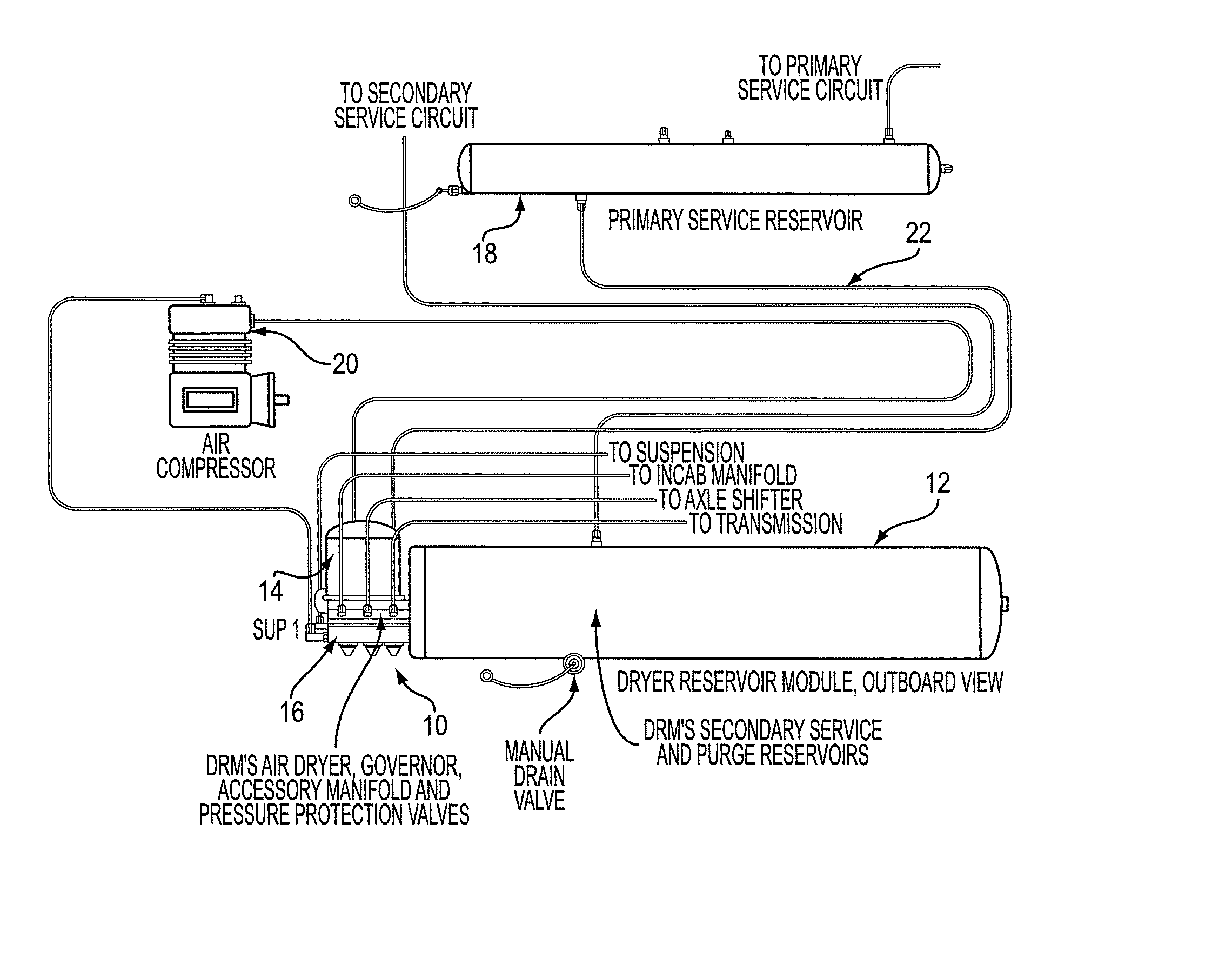
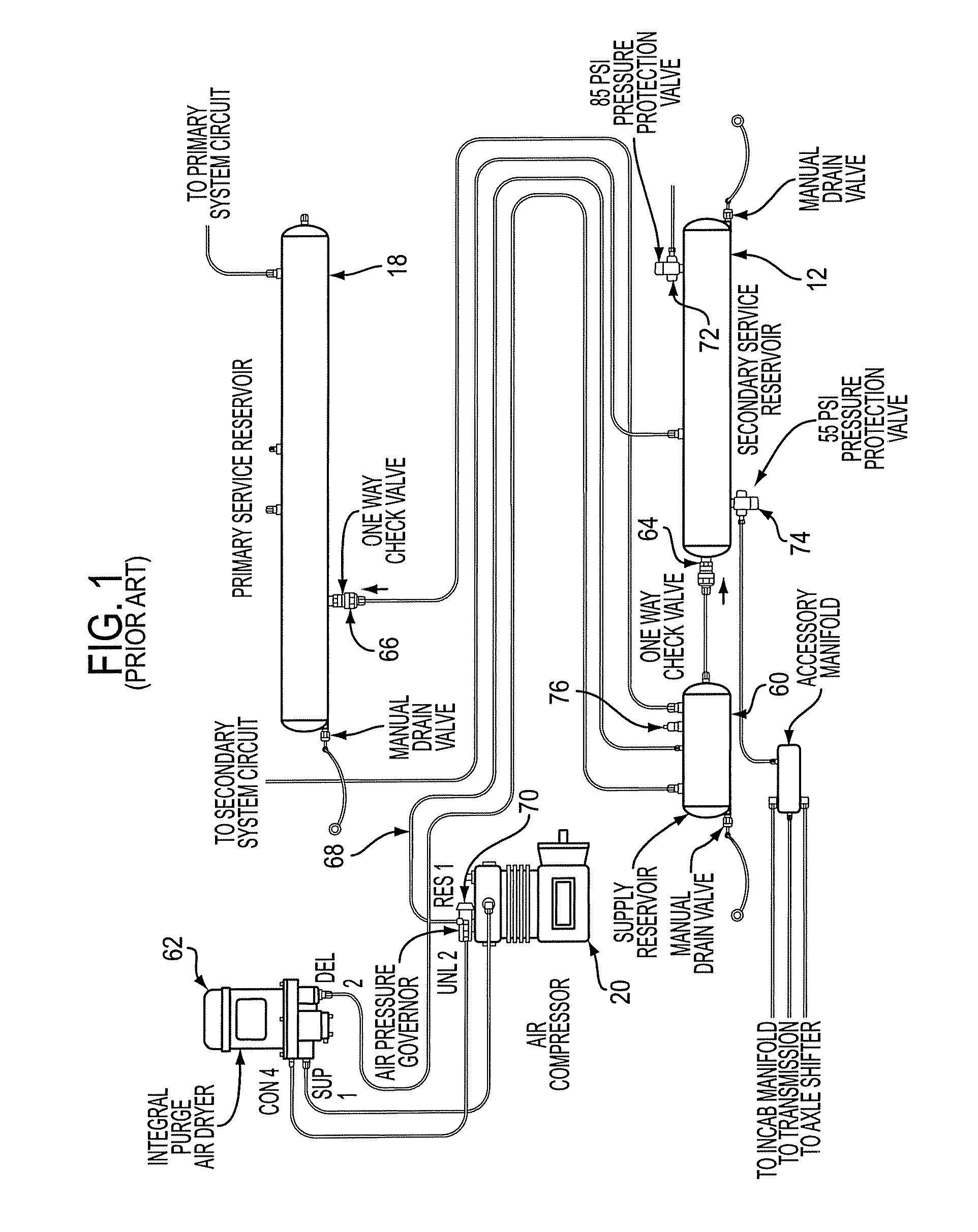
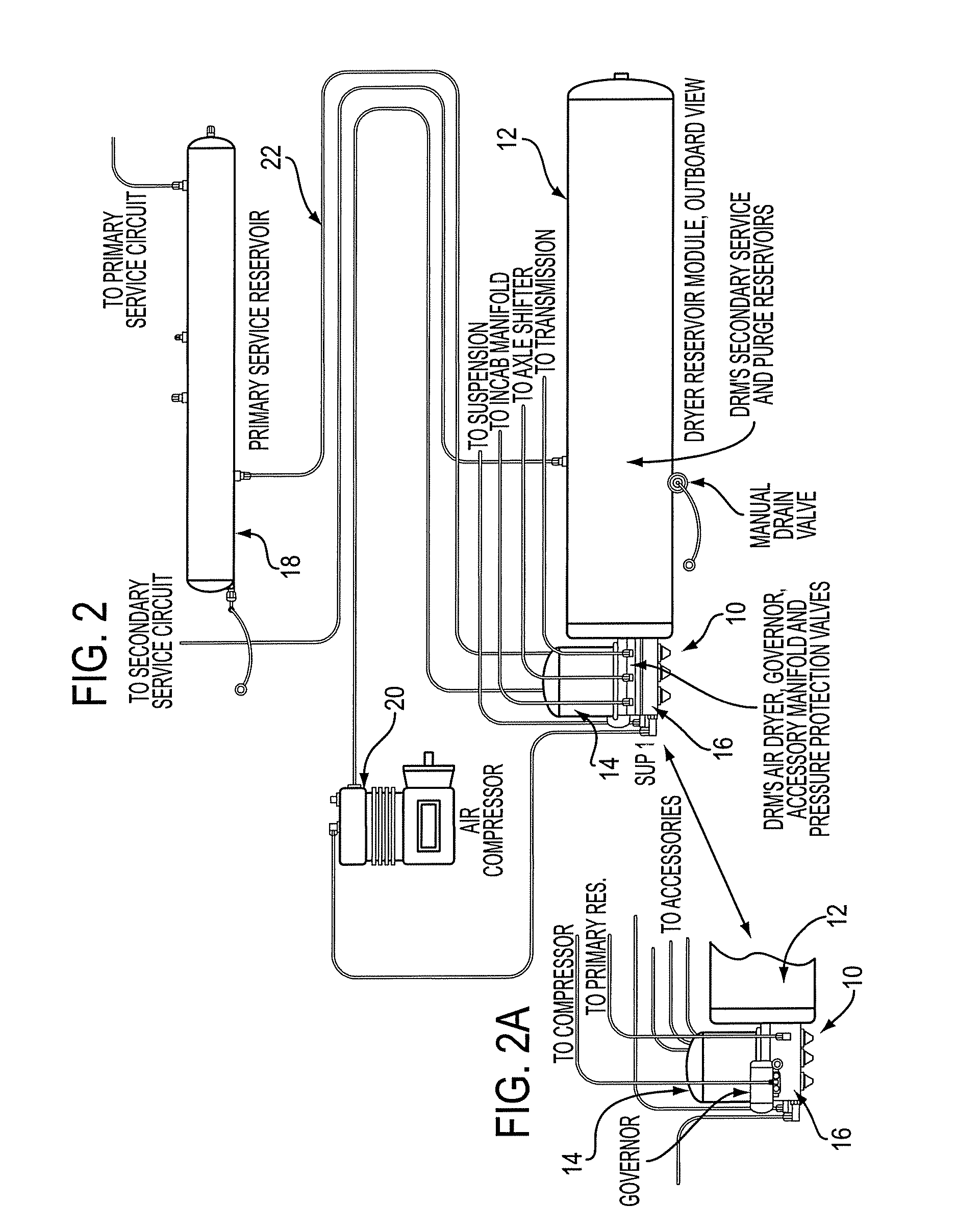
[0002] This invention relates to air dryers and more particularly to an air dryer and a reservoir, including a separate purge volume, constructed together as a module.
[0003] Air dryers have been used to dry the air in a heavy vehicle air brake system for many years. The advantages of clean and dry air in air brake systems has long been recognized, as moisture entrained in the air brake system may during cold weather operation cause the components of the air brake system to freeze, thus renderin...
PUM
 Abstract
Description
Claims
Application Information