Secondary Retention Device for Bi-Parting Doors

a technology for holding devices and doors, which is applied in the direction of wing accessories, wing arrangements, and lock applications, etc., can solve the problems of broken mechanical connection between the door panel and the door operator mechanism, and achieve the effect of reducing the cost or complexity of the door operator and avoiding a single-point failure mod

Active Publication Date: 2019-08-15
WESTINGHOUSE AIR BRAKE TECH CORP
View PDF0 Cites 0 Cited by
  • Summary
  • Abstract
  • Description
  • Claims
  • Application Information

AI Technical Summary

Benefits of technology

[0004]According to an example of the present disclosure, a retention mechanism for a bi-parting transit vehicle door operator is provided to mitigate a single-point failure mode in the door operator while not appreciably increasing the cost or complexity of the door operator. Examples of transit vehicles that incorporate such bi-parting door operators are rail transit cars. According to this example, the retention mechanism includes a door panel suspension roller or slider assembly fixed with respect to the door frame and a door panel suspension track attached to the door panels and movable along with the door panels. The retention mechanism provides a simple means of maintaining a door panel in a closed position subject to a mechanical failure in the door operator mechanism.

Problems solved by technology

In the event of a mechanical failure of a component of such assemblies involved in the motion transfer from the door operator mechanism to the door panel, such as a broken door arm or a broken or defective drive nut, the mechanical connection between the door panel and the door operator mechanism may become broken such that the door panel is able to slide freely when the door panel should be locked in a closed position.

Method used


Image

  • Secondary Retention Device for Bi-Parting Doors
  • Secondary Retention Device for Bi-Parting Doors
  • Secondary Retention Device for Bi-Parting Doors

Examples


Embodiment Construction

[0021]For purposes of the description hereinafter, the terms “end”, “upper”, “lower”, “right”, “left”, “vertical”, “horizontal”, “top”, “bottom”, “lateral”, “longitudinal”, and derivatives thereof shall relate to the invention as it is oriented in the drawing figures. However, it is to be understood that the invention may assume various alternative variations and step sequences, except where expressly specified to the contrary. It is also to be understood that the specific devices and processes illustrated in the attached drawings, and described in the following specification, are simply exemplary embodiments or aspects of the invention. Hence, specific dimensions and other physical characteristics related to the embodiments or aspects disclosed herein are not to be considered as limiting.

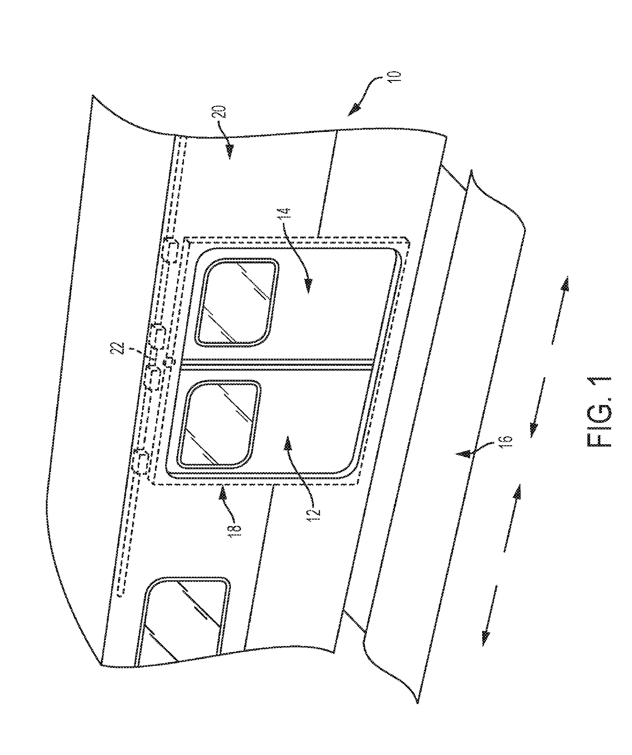
[0022]With reference to FIG. 1, a transit vehicle 10, such as a subway car, trolley car, other rail transit vehicle, or similar vehicle, is shown according to an example of the present disclosure. ...


PUM


Abstract

A retention mechanism for a pair of bi-parting doors of a transit vehicle includes a first track connected to a first door of the pair; a second track connected to a second door of the pair; a first retention assembly connected to the transit vehicle and configured to retain the first track in the closed position; a second retention assembly connected to the transit vehicle and configured to retain the second track in the closed position; a first engagement member connected to the second track, the first engagement member being configured to engage the first retention assembly to cause the first retention assembly to move to retain the first track in the closed position when the second track is in the closed position; and a second engagement member connected to the first track, the second engagement member being configured to engage the second retention assembly to cause the second retention assembly to move to retain the second track in the closed position when the first track is in the closed position.

Description

BACKGROUND OF THE INVENTIONField of the Invention[0001]The present invention relates generally to a retention mechanism for a transit vehicle door and, in particular, to a retention mechanism that is operated to retain the transit vehicle door in the event of a failure in a door operator system.Description of Related Art[0002]Transit vehicles are provided with bi-parting door assemblies that include door operator mechanisms to move the door panels between open and closed positions upon command from a central control. Examples of such bi-parting door assemblies are provided in U.S. Pat. No. 7,228,804 to Stojc et al., U.S. Pat. No. 6,032,416 to Springer et al., U.S. Pat. Nos. 6,539,669 and 6,684,567 to Heidrich et al., and in International Application Publication No. WO 2017 / 176831 to Stojc et al. The disclosures of each the above-mentioned publications is incorporated by reference in its entirety as set forth herein.[0003]In the event of a mechanical failure of a component of such as...

Claims


Application Information

Patent Timeline
Patent Type & Authority Applications(United States)
IPC IPC(8): E05C3/12E06B3/46E05C3/00E05C19/02E05D15/06
CPCE05C3/124E06B3/4636E05C3/006E05C19/02E05D15/063E05Y2201/622E05Y2600/456E05Y2900/51E05Y2900/531E05B65/0823E05B65/0847E05B77/52E05B83/363E05Y2201/22E05Y2201/606E05Y2201/684E05Y2800/40E05Y2800/25E05F15/40E05F15/632E05F15/655
Inventor PROVENCHER, JOEYAUGER, JULIEN SAUVEUR SERGE
Owner WESTINGHOUSE AIR BRAKE TECH CORP
Why Eureka
Try Eureka