Handy thermal head printer

a printer and thermal head technology, applied in the field of handy thermal head printers, can solve the problems of limited printing area, damaged entire unit, and inability to print in the non-printable area,

Inactive Publication Date: 2004-04-15
FUJITSU FRONTECH LTD
View PDF6 Cites 96 Cited by
  • Summary
  • Abstract
  • Description
  • Claims
  • Application Information

AI Technical Summary

Problems solved by technology

However, as marks are printed beforehand on the printable surface of the roll paper R1, the non-printable area can not be used for printing.
In other words, in this conventional printer 10 there is a problem in that the area where printing can be done is restricted to the area other than the

Method used


Image

  • Handy thermal head printer
  • Handy thermal head printer
  • Handy thermal head printer

Examples


Embodiment Construction

[0067] An exemplary embodiment of the printer according to the present invention is explained in detail with reference to the accompanying drawings.

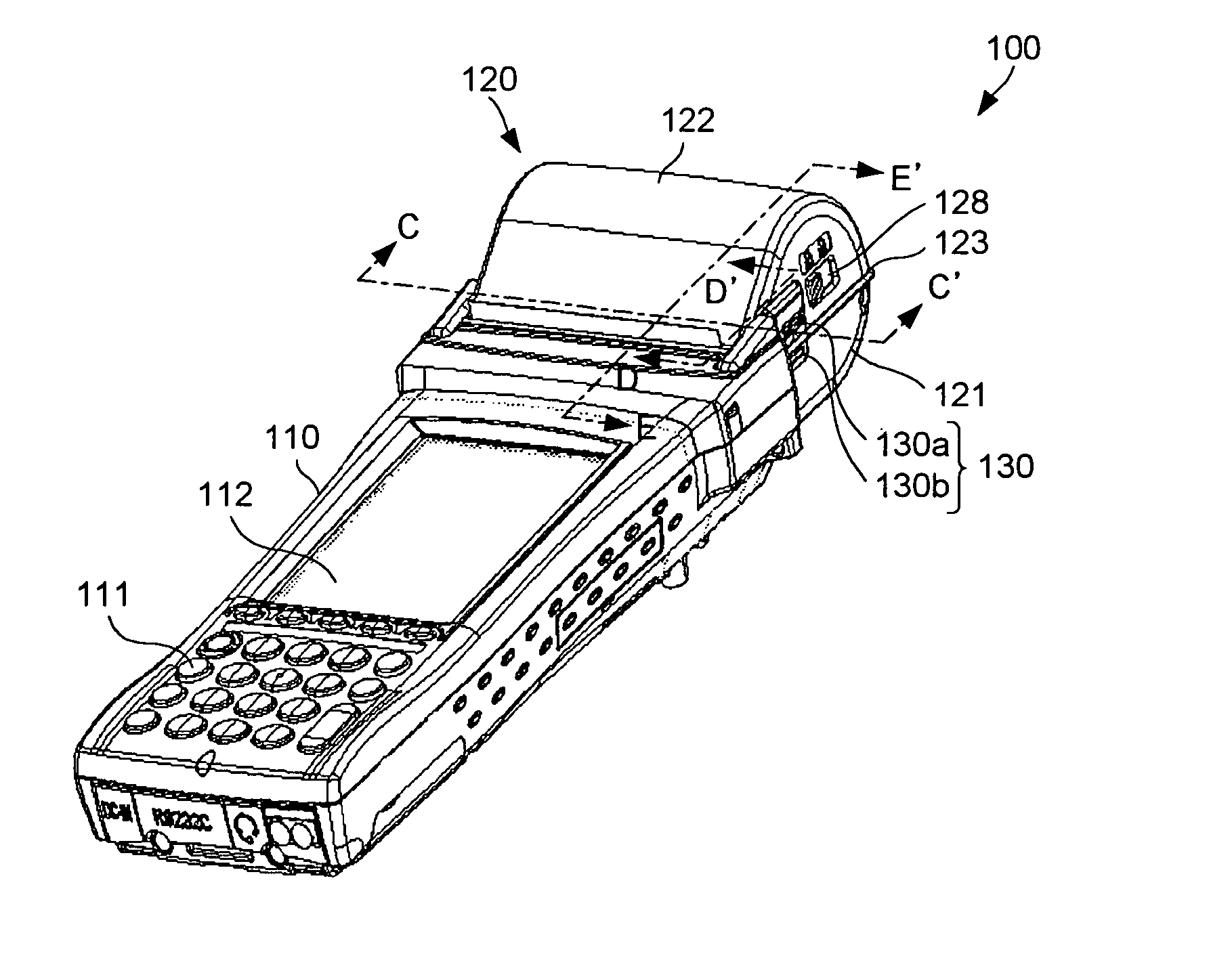
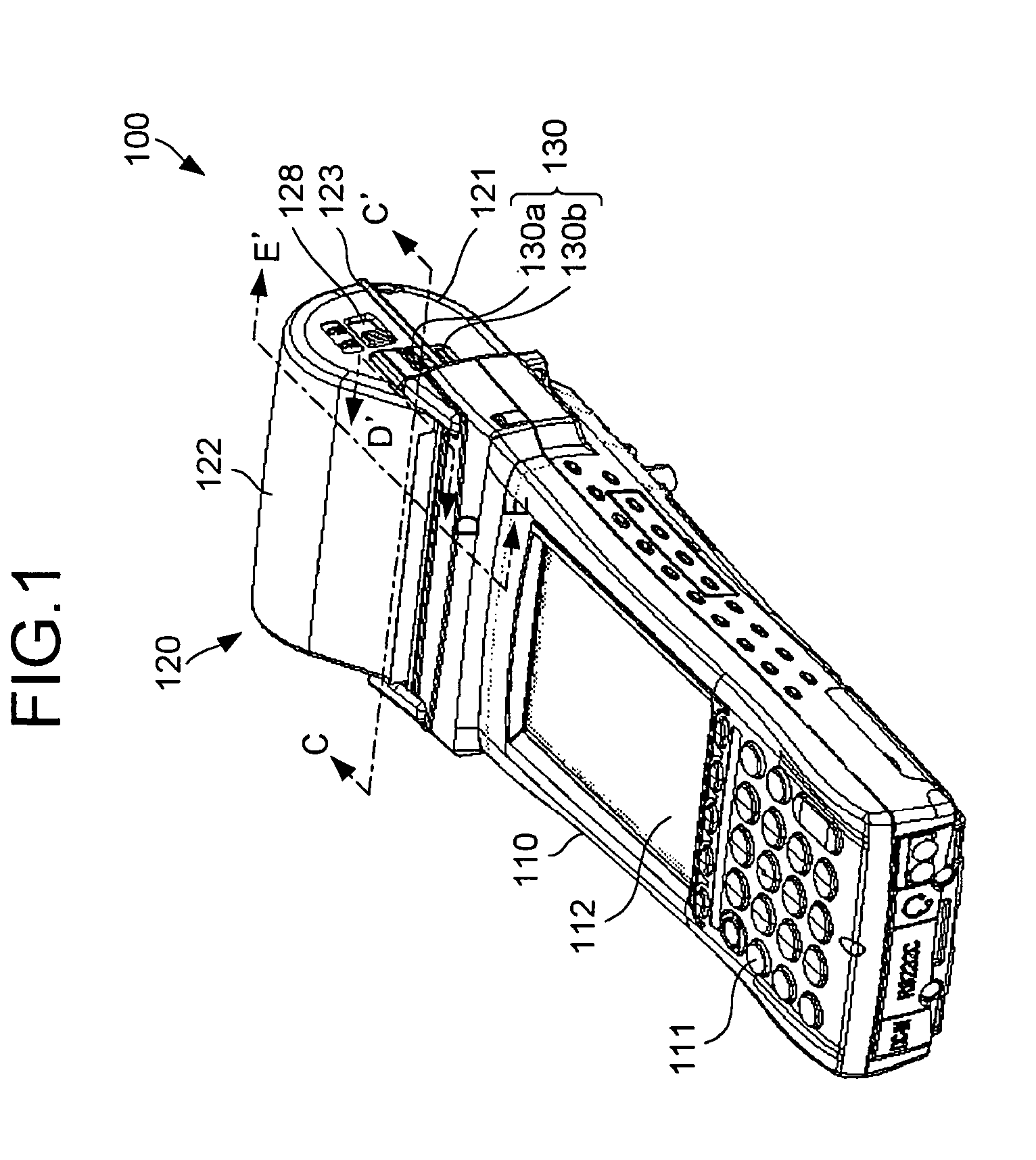
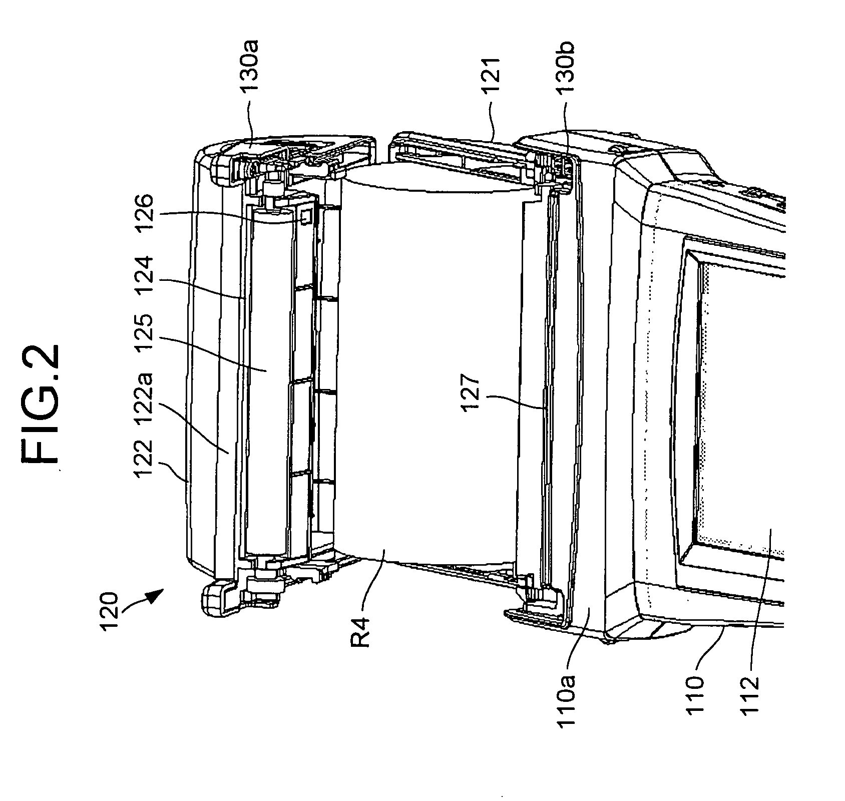
[0068] FIG. 1 is a perspective view of the external configuration of the printer 100 according to an exemplary embodiment of the present invention. FIG. 2 is a perspective view of a printer unit 120 of the printer 100 and shows that a roll paper R4 is set in the printer unit 120. FIG. 3 is a cross sectional view along the line C-C' shown in FIG. 1. FIG. 4 is a cross sectional view along the line D-D' shown in FIG. 1. FIG. 5A shows a state in which the printer unit is open, FIG. 5B is an enlarged view of a portion near a contact unit 130b, and FIG. 5C is an enlarged view of a portion near a contact unit 130a. FIG. 6 is a cross sectional view along the line E-E' shown in FIG. 1.

[0069] The printer 100 is used as a handy terminal. For example, the printer 100 has the function of printing information relating to electricity bills, product sal...


PUM


Abstract

A printer has a main body and a printer unit that is fixed to the main body. The printer unit has an upper cover and a lower cover. The lower cover is attached to the main body and the upper cover is fixed to the lower cover. A hollow space is formed between the upper and lower covers and a printing paper is set in this space. A sensor is provided in the upper cover and it detects a mark on the non-printable surface of the printing paper. One protrusion is provided in each of the upper and lower covers such that the protrusions make an electrical contact when the upper and lower covers are closed. A control unit is provided in the main body and it is electrically connected to the mark detection unit through the protrusions on the upper and lower covers and it controls various operations of the printer.

Description

[0001] 1) Field of the Invention[0002] The present invention relates to a handy thermal head printer.[0003] 2) Description of the Related Art[0004] FIG. 7 is a partially cut perspective view of a conventional printer 10. The printer 10 is handheld by a user and has the function of printing electricity bills, product sales information or the like. This printer 10 has a main body 11 that houses a printer substrate (not shown). This printer substrate holds a control unit (not shown) that controls the printing process.[0005] The main body 11 has a clam-type printer unit 12 provided at one end 11a thereof. The printer unit 12 has a lower cover 13 and an upper cover 14. The lower cover 13 and the upper cover 14 are joined at a joint 15 so that the upper cover 14 can be freely opened and closed. As shown in FIG. 8, which is a cross sectional view of the printer 10 along the line A-A' shown in FIG. 7, a roll paper R1 is loaded in the hollow space between the lower cover 13 and the upper cov...

Claims


Application Information

Patent Timeline
IPC IPC(8): B41J2/325B41J3/36B41J11/42B41J11/46B41J15/04B41J29/00
CPCB41J3/36B41J15/042B41J11/46
Inventor SHIMODA, YUJI
Owner FUJITSU FRONTECH LTD
Why Eureka
Try Eureka