Retractable self rolling blind awning or cover apparatus

a self-rolling, blind awning technology, applied in the direction of sunshades, curtain suspension devices, building components, etc., can solve the problems of increasing the difficulty of operation, limiting the useful span of the blind awning which could be conveniently achieved,

Inactive Publication Date: 2004-07-22
ABOULOUKME ISSAM
View PDF5 Cites 4 Cited by
  • Summary
  • Abstract
  • Description
  • Claims
  • Application Information

AI Technical Summary

Benefits of technology

0005] It is therefore an object of the present invention to overcome or at least ameliorate some or all of the foregoing disadvantages by providing an improved retractable rolling apparatus, relying in principle on the use of more than one sheet of material (and especially two sheets) rolled about the keyway tube of an otherwise conventional spring type blind or awning mechanism each of the sheets extending generally (but not necessarily) in opposite directions, so that in the case of two sheets of material pulled in opposite directions, the span of extended material is effectively doubled for each revolution of the tube, when compared with a single sheet.

Problems solved by technology

In such situations however, especially in horizontal arrangements such as pool covers or external awnings, there is a limit to the useful span of cover which could be conveniently achieved (ie considering the length of material which may be unrolled), requiring larger spring mechanisms to accommodate increasing lengths of material to be extended and rewound.
This of course means increasing difficulty of operation, as it becomes necessary to pull against the increasing tension of larger springs over increasing lengths of material required to be unrolled.

Method used


Image

  • Retractable self rolling blind awning or cover apparatus
  • Retractable self rolling blind awning or cover apparatus
  • Retractable self rolling blind awning or cover apparatus

Examples


Embodiment Construction

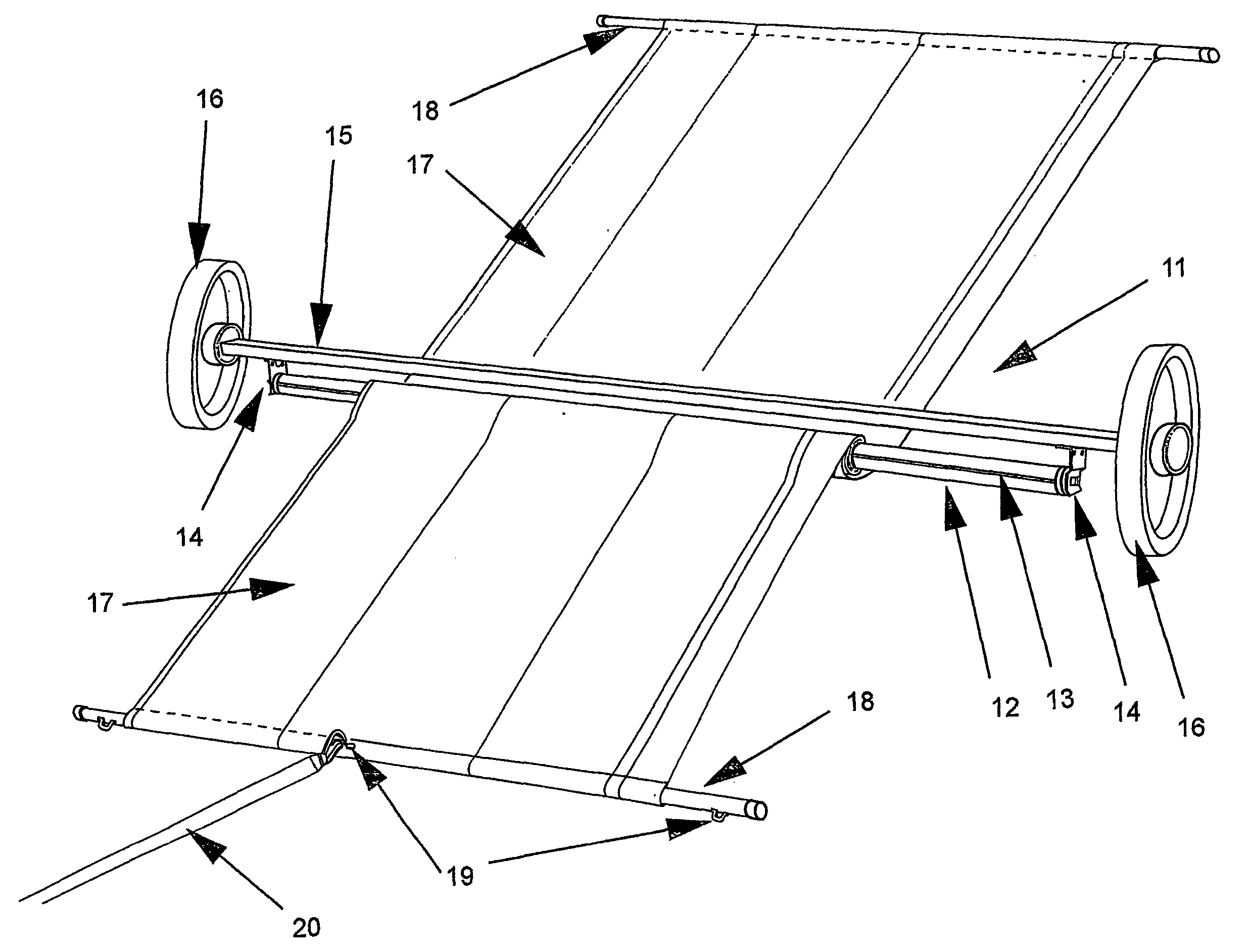
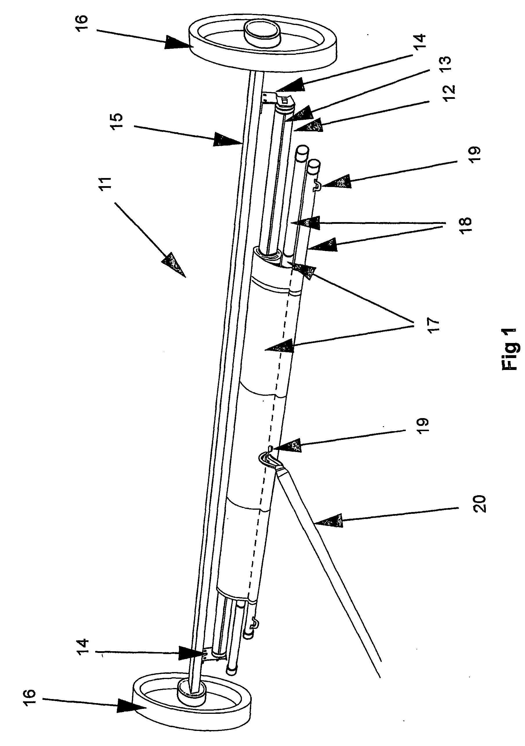
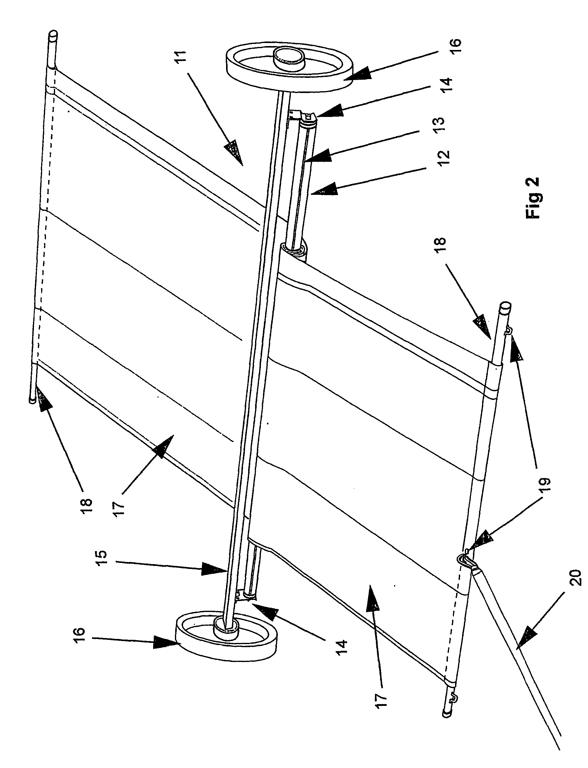
[0032] Referring generally to the drawings and in particular to FIGS. 1 and 2 there is depicted a rolling apparatus, generally referenced 11, comprising a key-way tube 12, having a key-way 13 which runs along the length thereof. The tube 12 is supported in brackets 14, which in turn are attached to a frame member 15 which acts as a tension bar 15. Tension bar 15 is fitted at each end with wheels 16 which support the rolling apparatus 11 and allows it to roll over any suitable surface or in any suitable track (not illustrated).

[0033] Two sheets of cover material 17 are wound about key-way tube 12. The inner edges of each sheet of material 17, not visible, are fitted within the key-way slot 13 which runs along the length of the tube 12, in known fashion (except that two sheets rather than one sheet are fitted). The two sheets of material 17 are each provided with a bar member 18 at their free ends to assist in pulling the sheets and generally supporting the free ends thereof. One or m...


PUM


Abstract

A retractable self rolling blind, awning or cover apparatus (11), is disclosed in which there are two or more sheets of fabric or other suitable material (17) affixed and wound conjointly about a keyway tube (12) which is supported between suitable brackets (14) mounted on a tension bar (15). The keyway tube is mounted so that it is parallel with the tension bar and the tube is fitted with a conventional spring mechanism for use with blinds, awnings and the like. The spring mechanism is pretensioned so as to cause the sheets of fabric to be rewound about the keyway tube when one or more of the sheets of fabric is released from its extended or unwound position. The keyway tube and tension bar are allowed to travel during unwinding and winding up of the fabric, preferably assisted by providing either the ends of the tube itself, or the ends of the frame in which such tube is mounted, with wheels or pulleys (16) depending on the particular use to which the apparatus is to be put.

Description

[0001] This invention relates to self-rolling apparatus based on a conventional spring mechanism for items such as blinds, awnings and covers. However, the invention should not be construed as being limited thereto and any similar arrangement where by the invention may be suitably adapted is meant to be encompassed including advertising screens and the like.[0002] Conventional spring blinds are provided with a so-called hollow keyway tube, onto which one end of suitable blind fabric or other material is attached, the remainder of the material being wrapped or rolled around the periphery of the tube. A spring mechanism is provided within the hollow tube, which is itself supported between suitable brackets. The blind fabric may be caused to unroll for any desired length (up to the limit of material rolled on the tube), usually by pulling on it, which causes the tube to rotate about its axis, thereby winding up (ie further tensioning) the spring mechanism. In a conventional, free-hangi...

Claims


Application Information

Patent Timeline
Patent Type & Authority Applications(United States)
IPC IPC(8): E04F10/02E06B9/40
CPCE04F10/02E06B9/40E04F10/0607
Inventor ABOULOUKME, ISSAM
Owner ABOULOUKME ISSAM
Why Eureka
Try Eureka