Manufacturing method of phosphor or scintillator sheets and panels suitable for use in a scanning apparatus

a technology of phosphor or scintillator and scanning apparatus, which is applied in the direction of conversion screens, instruments, nuclear engineering, etc., can solve the problems of difficult to obtain a layer with a constant thickness, production methods cannot be used to produce high-quality screens, and large amount of expensive residues

Inactive Publication Date: 2004-11-04
AGFA NV
View PDF11 Cites 31 Cited by
  • Summary
  • Abstract
  • Description
  • Claims
  • Application Information

AI Technical Summary

Benefits of technology

0022] The above-mentioned advantageous effects have been advantageously realized by a particular manufacturing method having the specific features set out in claim 1. Specific features for preferred embodiments of the invention are set out in the dependent claims and in the drawings.
0023] Further advantages and embodiments of the present invention will become apparent from the following description and drawings.
0024] Following Figures represent an illustration of different embodiments of configurations related with the substrate to be coated and the apparatus wherein the coating process takes place. It is clear that these Figures, showing preferred embodiments of the coating methods according to the present invention, are in no way limited thereto.
0025] FIG. 1 shows a cylindrical vacuum chamber (1), containing an electrically heated oven (2) and a refractory crucible, tray or boat (3) containing a mixture of raw materials (4) which should be vaporized in order to be deposited onto a flexible sheet (5). The flexible sheet (5) is supported by a cooled--supporting--roller (6), thermally isolated from said flexible sheet (5) by a thermal isolation layer (7) and by heat-resisting coiled springs (8) mounted circumferentially onto said cylinder, further interconnecting both ends of said flexible sheet (5). Heating of said flexible sheet (5) proceeds by means of infrared heater (9) and reflector cage (10). Pyrometer (11) allows measurement of the temperature. The flexible sheet (5) is moving continuously or discontinuously in a forward direction through a vapor stream (16) provided by the heated mixture of raw materials (4) as a source for said vapor stream (16). Baffles (12) and (13) restrict vapor deposition to a selected part of sheet (5), mounted onto the roller (6). Refractory boat or tray (3) is covered with metallic raster (14), which avoids formation of pits (and unevenness) on the coated phosphor layer, deposited onto the flexible sheet (5). A cooled baffle (17) may be moved to shut off the surface to be coated from or expose the surface to be coated to the vapor stream.
0026] Optionally there can be a separation (15) between the evaporation part (18) and the heating part (19).
0027] FIG. 2 shows vacuum chamber (1), a flexible sheet(S) that is stretched around four conveying rollers (20), moving continuously or discontinuously in a forward direction through a vapor stream (16), provided by the mixture of raw materials (4) present in the tray or boat (3) and heated to provide a vapor source generating said vapor stream (16), in order to provoke a phosphor layer to be deposited onto the flexible sheet (5) in one step (passage or transit through the vapor stream (16) in one step) or in several successive steps (more than one passage or transit through the vapor stream (16)) and wherein the flexible sheet (5) does not leave the vacuum chamber (1). The illustrated travelling pathway (21) of the flexible sheet (5) is not limitative. Another construction could be the use of smaller flexible sheets that are mounted on a flexible support material that is stretched around the conveying rollers (20).

Problems solved by technology

However, this production method can not be used to produce high quality screens with every arbitrary phosphor available.
Moreover, when square or rectangular panels are desired, quite a lot of expensive residue is created while not being deposited onto the plate, rotating with a circular symmetry above the vapor source.
In addition, when depositing material from a fixed source onto such a rotating substrate, it is difficult to obtain a layer with a constant thickness.
This creates a centro-symmetric thickness profile, which means that the thickness of the deposited layer is constant along neither of the sides of a rectangular substrate, unless special precautions are taken, e.g. use of a mask which will however lead to material losses.
Such an apparatus comprises a substrate holder conveyed from a loading chamber to an unloading chamber by a conveying mechanism, and provides coated panels limited in process yield.
In such a batch process a coating failure will generally lead to the complete loss of a panel.
Moreover there will always be a high loss of raw materials in such batch processes.
Lack of deformability of the substrate also limits the format of the coating of a phosphor or scintillator layer on a substrate to the largest cross section of the vacuum deposition chamber.

Method used


Image

  • Manufacturing method of phosphor or scintillator sheets and panels suitable for use in a scanning apparatus
  • Manufacturing method of phosphor or scintillator sheets and panels suitable for use in a scanning apparatus
  • Manufacturing method of phosphor or scintillator sheets and panels suitable for use in a scanning apparatus

Examples


##ventive example 2

Inventive Example 2

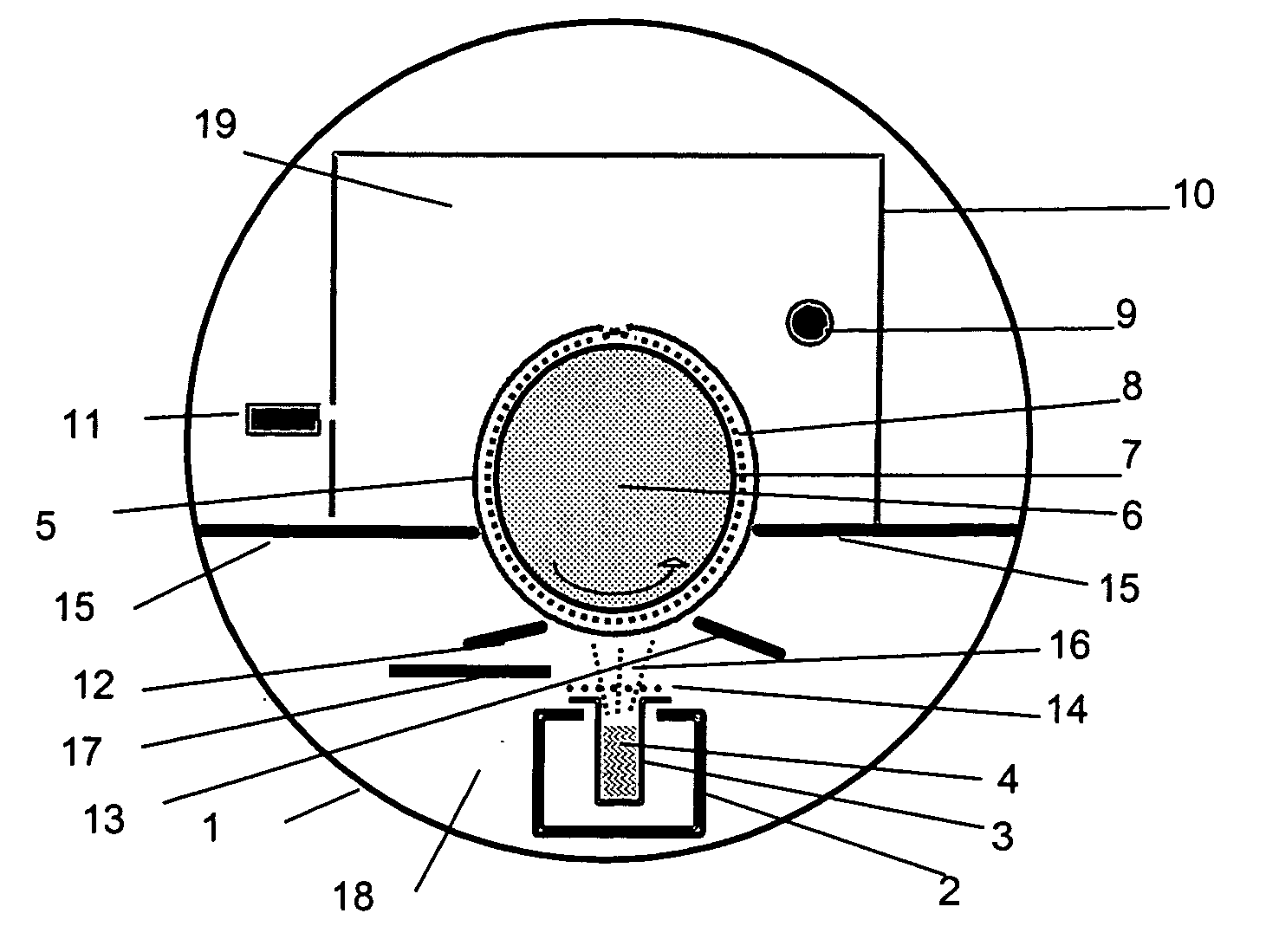
[0112] A CsBr:Eu photostimulable phosphor screen on flexible anodized aluminum was prepared in a vacuum chamber via thermal vapor deposition on a flexible anodized aluminum support, moving in such a way that the momentary magnitude of the velocity was constant over its whole area, starting from a mixture of CsBr and EuOBr as raw materials.

[0113] Referring to FIG. 1 the cylindrical vacuum chamber (1) with a diameter of 1.4 m and a length of 1.75 m was containing an electrically heated oven (2) and a refractory tray or boat (3) (dimensions of the elongated boat composed of "stainless steel 1.4828": 0.97 m (length).times.4.5 cm (width).times.6.8 cm (depth), having a wall thickness of 3 mm), in which 4 kg of a mixture (4) of CsBr and EuOBr in a 99.5% / 0.5% CsBr / EuOBr percentage ratio by weight were present as raw materials to become vaporized. The boat was covered with a metallic raster (14) having a mesh of 300 .mu.m in order to reduce the formation of pits during eva...

##ventive example 3

Inventive Example 3

[0131] A CsBr:Eu photostimulable phosphor screen was prepared in a vacuum chamber by thermal vapor deposition on a flexible anodized aluminum,that was supplied in a continuous fashion.

[0132] Referring to FIG. 8 a cylindrical vacuum chamber (1) with a diameter of 1.4 m and a length of 1.75 m was containing an electrically heated oven (2) and a molybdene tray or boat (3) (dimensions of the elongated boat: 0.97 m (length).times.1.40 cm (width).times.5.8 cm (depth), having a wall thickness of 3 mm), in which 1.6 kg of a mixture (4) of CsBr and EuOBr in a 99.5% / 0.5% CsBr / EuOBr percentage ratio by weight were present as raw materials in order to become vaporized. The vacuum chamber (1) further contained a roller supply (23) of anodized aluminum that was fed out in continuous sheet form (22), also called "web". The web was conveyed over a cooled guiding roller (6) with a diameter of 40 cm and collected on a winding roll (24), collecting the web after vapor deposition coa...


PUM

PropertyMeasurementUnit
thicknessaaaaaaaaaa
thicknessaaaaaaaaaa
thicknessaaaaaaaaaa

Abstract

In a method for coating a phosphor or a scintillator layer onto a flexible substrate, within a sealed zone maintained under vacuum conditions, by the step of vapor deposition, said phosphor or scintillator layer is, continuously or discontinuously, deposited onto said substrate, and said substrate is deformed at least before, during or after said step of vapor deposition, in order to provide the manufacturer, by a process of exceptionnally high yield, with large deposited phosphor or a scintillator sheets having constant speed and image quality properties, further offering availablity of all formats as desired for screens, plates or panels ready-for-use in a scanning apparatus in computed radiography, screen/film radiography and direct radiography.

Description

[0001] The present invention relates to a particular method of coating a layer from a vapor flow of raw materials on a flexible substrate. More particularly the present invention relates to the manufacturing or production of scintillator or phosphor sheets, used in screens, panels or plates suitable for use in high energy radiation detection and imaging and, more particularly, in computed radiography, screen / film radiography and direct radiography.[0002] In radiography the interior of objects is reproduced by means of penetrating radiation, which is high energy radiation also known as ionizing radiation belonging to the class of X-rays, .gamma.-rays and high-energy elementary particle rays, e.g. .beta.-rays, electron beam or neutron radiation.[0003] For the conversion of penetrating radiation into visible light and / or ultraviolet radiation "luminescent" substances, called "phosphors", are used. Cathodoluminescent phosphors employed e.g. in CRT screens exhibit two related luminescent...

Claims


Application Information

Patent Timeline
Patent Type & Authority Applications(United States)
IPC IPC(8): C09K11/77C23C14/56G21K4/00
CPCC09K11/7733C23C14/562G21K4/00
Inventor LAMOTTE, JOHNVERREYKEN, GUIDOLEBLANS, PAUL
Owner AGFA NV
Why Eureka
Try Eureka