Prosthetic socket with self-contained vacuum reservoir

a prosthetic socket and vacuum reservoir technology, applied in the field of vacuum suspension prosthetic sockets, can solve the problems of unwieldy arrangements, add to the weight of the prosthetic device, and separate the prosthetic socket from the residual limb

Active Publication Date: 2004-12-23
OSSUR HF
View PDF2 Cites 85 Cited by
  • Summary
  • Abstract
  • Description
  • Claims
  • Application Information

AI Technical Summary

Problems solved by technology

Obviously, with a vacuum suspension system, any significant loss of vacuum will result in separation of the prosthetic socket from the residual limb unless an additional element is provided to retain the socket attached to the residual limb.
Such arrangements are unwieldy and tend to add to the weight of the prosthetic device suspended from the prosthetic socket.
Movement of the prosthetic socket disclosed by this patent tending to separate the socket from the residual limb would result in deformation of the diaphragm in a reverse direction into the chamber thereby creating insecurity on the part of the amputee as

Method used


Image

  • Prosthetic socket with self-contained vacuum reservoir
  • Prosthetic socket with self-contained vacuum reservoir
  • Prosthetic socket with self-contained vacuum reservoir

Examples


Embodiment Construction

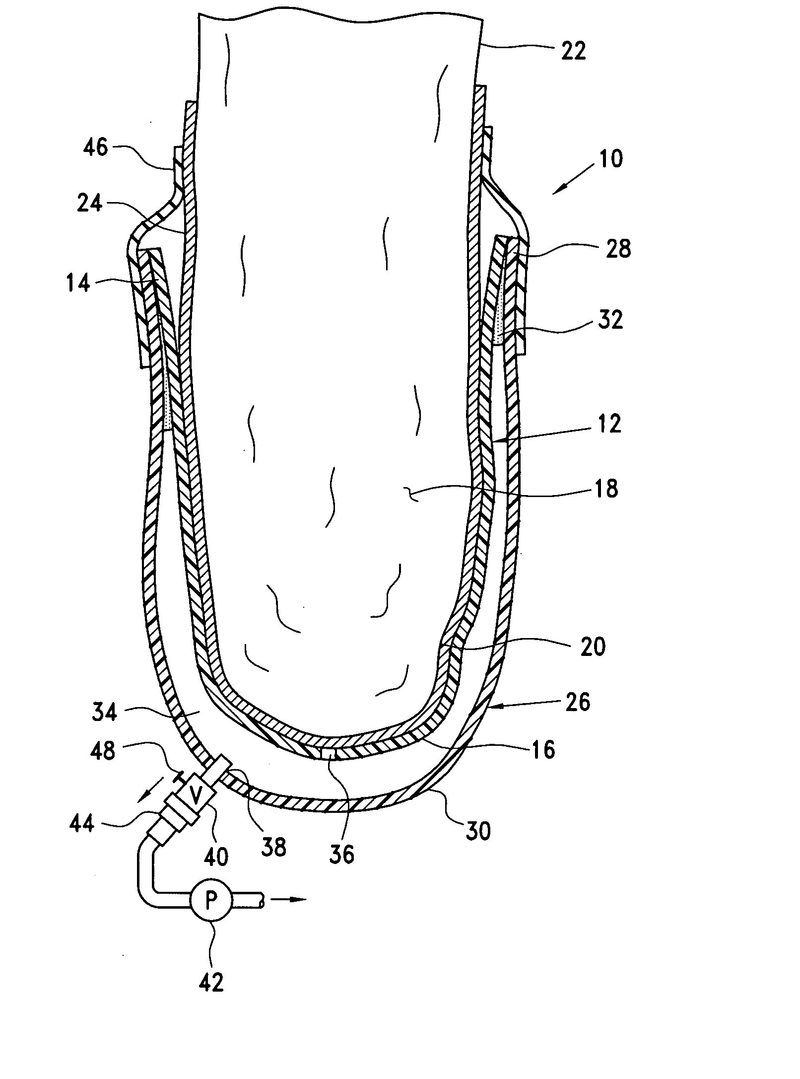
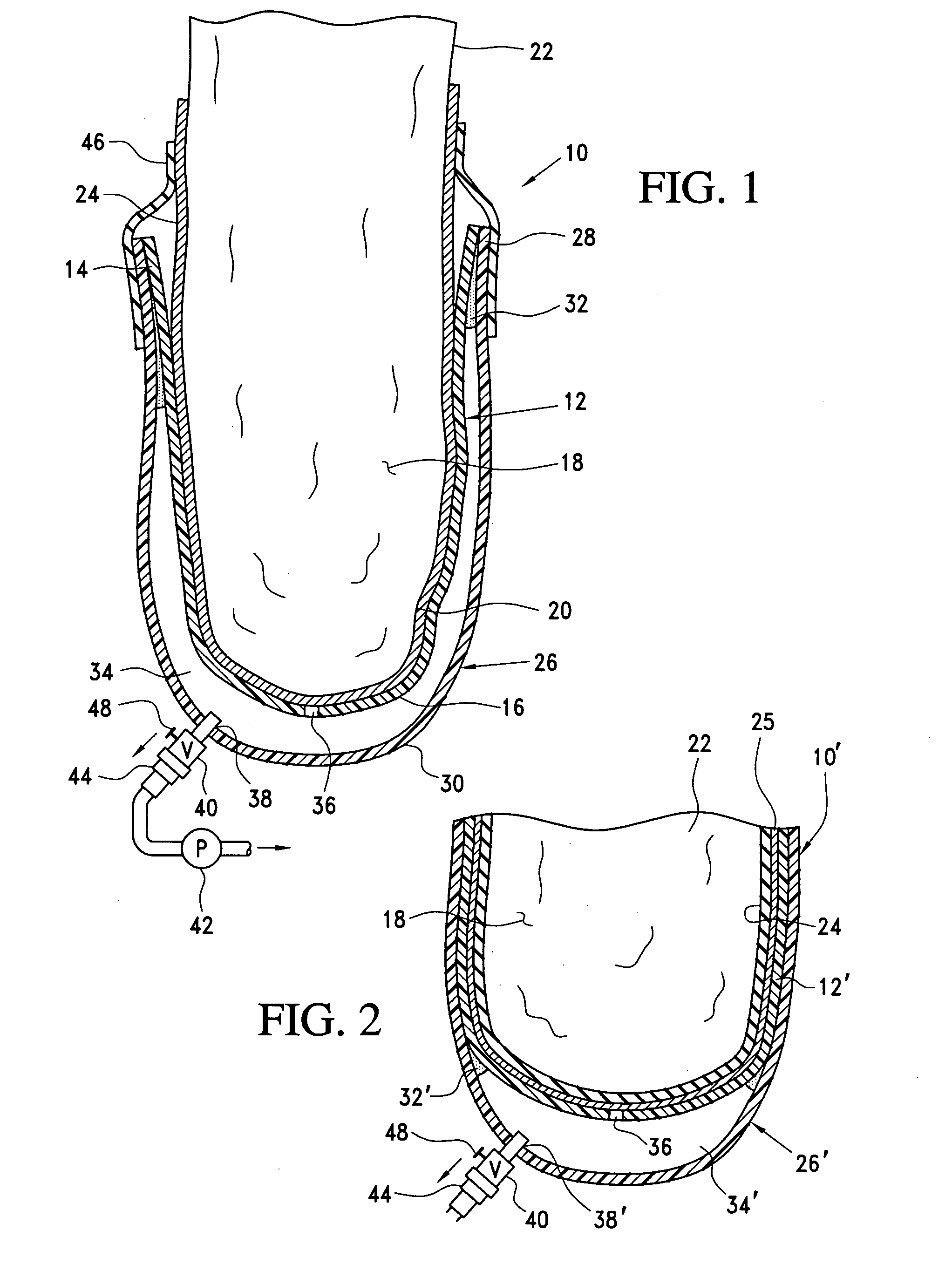
[0034] With reference to the appended views, preferred embodiments of the present invention are illustrated to provide exemplary examples of prosthetic sockets arranged to carry a vacuum reservoir chamber within the socket to provide a source of sub-atmospheric pressure in the socket sufficient to maintain the distal end portion of a residuum of an amputee within a rigid inner socket element member so that a partial vacuum may be maintained between the residuum and the inner rigid socket element member during implementation of the prosthetic socket constructed in accordance with the invention. By providing a sub-atmospheric or vacuum chamber reservoir within the socket assembly, the need for a separate vacuum reservoir chamber is eliminated along with a structural complexity, weight and conduits associated with an external vacuum reservoir.

[0035] With reference to FIG. 1, an example of a prosthetic socket 10 embodying the invention comprises an assembly of a rigid, structural, load ...


PUM

PropertyMeasurementUnit
Fractionaaaaaaaaaa
Volumeaaaaaaaaaa
Areaaaaaaaaaaa

Abstract

A prosthetic socket having a self-contained vacuum reservoir chamber includes a rigid, load-bearing inner socket member for receiving a residual limb and an outer, rigid, load-bearing wall section attached to the inner wall section in a manner providing a vacuum reservoir chamber between the inner wall and the outer wall section. The vacuum reservoir chamber communicates with the inner volume of the inner wall through a vacuum transfer port and the vacuum reservoir chamber may be evacuated via an evacuation port having an appropriate one-way check valve permitting withdrawal of air from the vacuum reservoir chamber while preventing ingress of air into the chamber. A method for making the prosthetic socket is disclosed.

Description

[0001] This application claims the benefit of U.S. provisional patent application No. 60 / 480,350 filed Jun. 20, 2003.[0002] 1. Field of the Invention[0003] This invention relates to vacuum suspension prosthetic sockets.[0004] 2. Discussion of Related Art[0005] Amputees have retained prosthetic devices on their residual limbs using various vacuum or suction arrangements for many years, particularly since the advent of soft cushion liners that are worn between the residual limb and the prosthetic socket. Typically, a one-way valve is provided at a distal end of an otherwise closed socket arranged to receive the distal end portion of a residual limb whereby air in front of the distal end of the residual limb may be exhausted until the residual limb and its donned liner are fully inserted into the socket.[0006] The one-way valve thereafter is maintained in a closed condition and forces tending to separate the prosthetic socket from the residual limb are resisted by induced sub-atmospher...

Claims


Application Information

Patent Timeline
IPC IPC(8): A61F2/50A61F2/80B29C70/30
CPCA61F2/5046A61F2/80A61F2002/5053A61F2002/5055A61F2002/805A61F2002/807B29C70/30B29L2031/7532
Inventor PATTERSON, WILLIAM STANPATTERSON, WILLIAM E.
Owner OSSUR HF
Why Eureka
Try Eureka