Predictive maintenance and initialization system for a digital servovalve

Active Publication Date: 2005-01-06
CONTROL COMPONENTS INC
View PDF11 Cites 71 Cited by
  • Summary
  • Abstract
  • Description
  • Claims
  • Application Information

AI Technical Summary

Benefits of technology

[0015] The present invention specifically addresses and alleviates the above reference deficiencies associated with servovalve systems utilizing stepper motors. More particularly, the present invention is an improved servovalve system having a position sensor and controller that utilizes a unique set of algorithms for detecting and monitoring a level of mechanical resistance occurring within a servovalve assembly. The position sensor and controller also cooperate to allow for simple and reliable initial

Problems solved by technology

Unfortunately, the accuracy with which the stepper motor tracks the sequence of command signals may diminish over time due to the buildup of mechanical impediments or resistance between the spool and the housing.
Such mechanical resistance may include excessive friction between the spool and the housing.
In such systems, the optical encoder may generate an error signal if the stepper motor fails to track the desired position.
However, without the capability to continuously monitor mechanical resistance between the spool and the housing, inaccurate positioning of the piston within the cylinder may occur such that safety may be compromised.
In the case of very large servovalves requiring multiple rotations of the stepper motor to achieve the desired spool position, such springs become unwieldy arrangements of clock springs that may be impractical to implement.
U

Method used


Image

  • Predictive maintenance and initialization system for a digital servovalve
  • Predictive maintenance and initialization system for a digital servovalve
  • Predictive maintenance and initialization system for a digital servovalve

Examples


Embodiment Construction

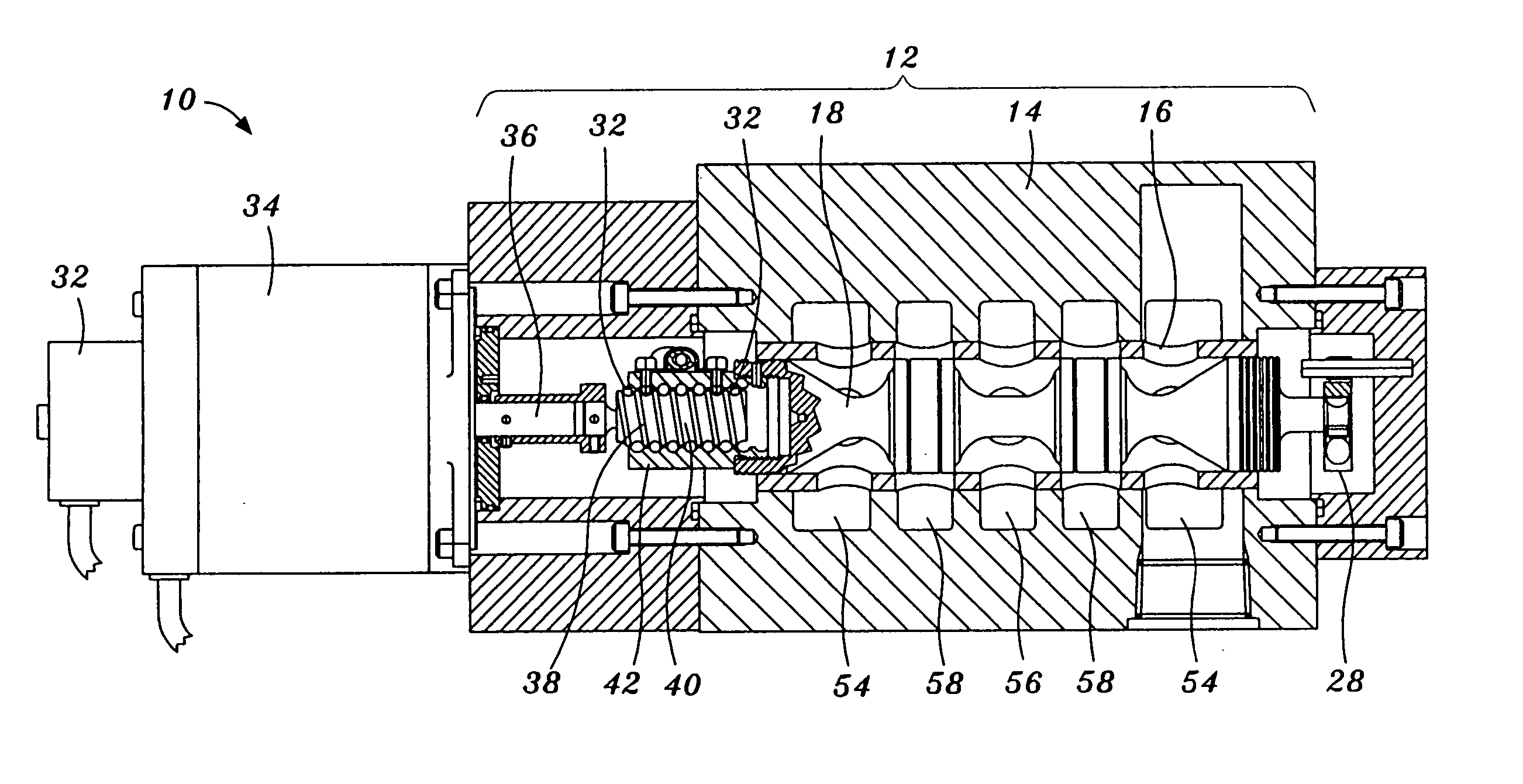
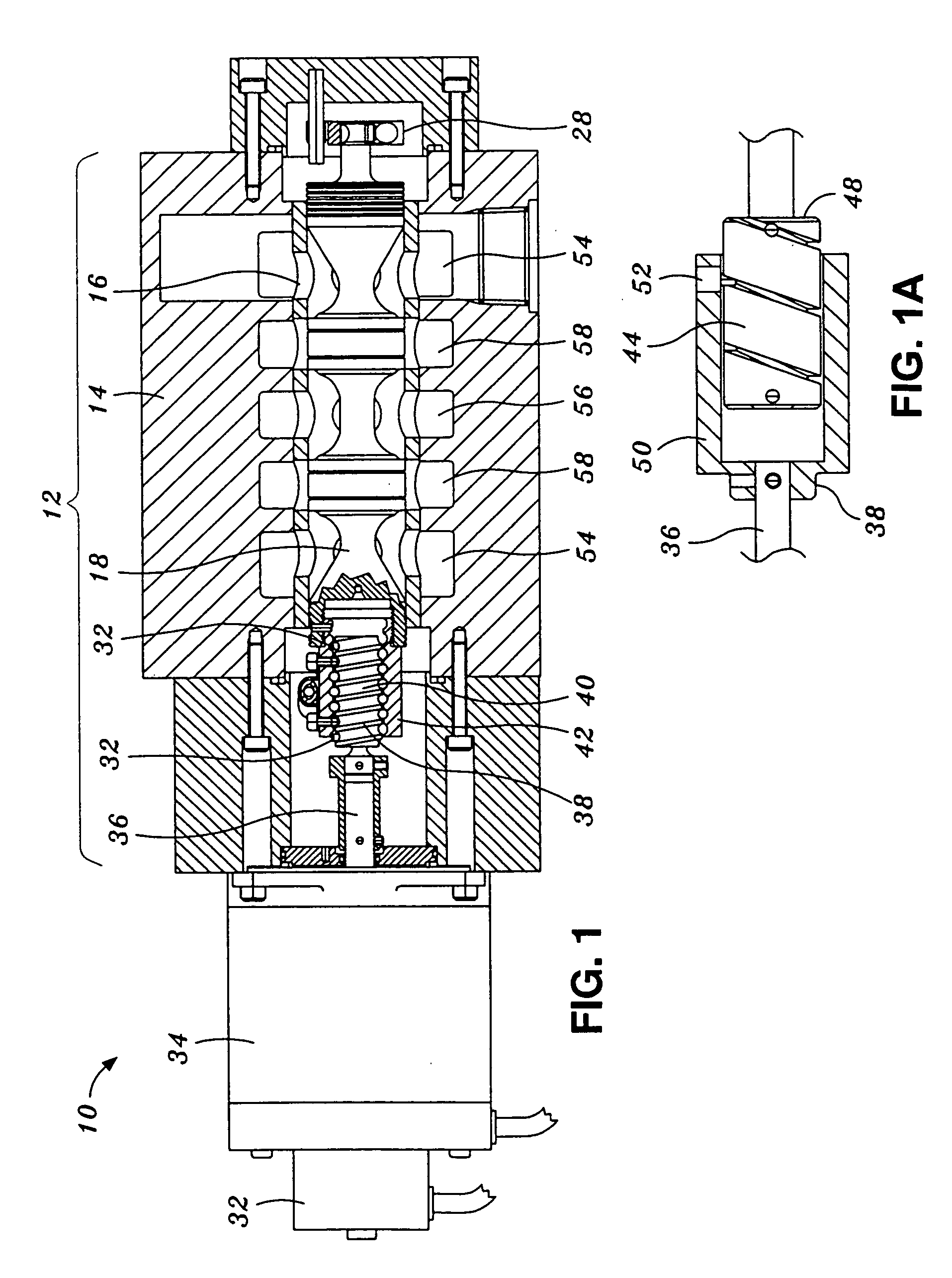
[0023] Referring now to the drawings wherein the showings are for purposes of illustrating the present invention and not for purposes of limiting the same, FIG. 1 illustrates a servovalve system 10 of the present invention comprising a rotary reversible stepper motor 34 connected to a servovalve assembly 12 and illustrating a position sensor 32 electronically coupled to the stepper motor 34. The servovalve assembly 12 includes a spool 24 slidably disposed within a housing 14. The stepper motor 34 is operatively connected to the spool 24 and is configured to move the spool 24 relative to the housing 14.

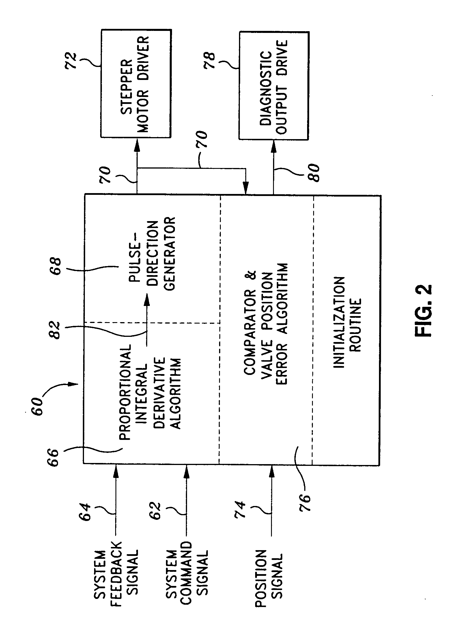
[0024] A controller 60, illustrated in block diagram in FIG. 2, is also included in the servovalve system 10. The controller 60 may be electronically coupled to the stepper motor 34 and is configured to provide microstepping control over the stepper motor 34. The controller 60 and position sensor 32 cooperate to regulate the stepper motor 34 such that the spool 24 may be positioned re...


PUM


Abstract

Provided is a servovalve system for regulating fluid flowing within a fluid circuit. The servovalve system comprises a housing, a spool slidably disposed within the housing, a stepper motor operatively connected to the spool, and a controller and a position sensor electronically connected to the stepper motor. The controller generates driver signals representative of a desired amount of stepper motor rotation in order to cause the stepper motor to effectuate spool motion relative to the housing. The position sensor senses an actual amount of stepper motor rotation and generates a quantity of position signals representative thereof. The controller determines a signal ratio of the quantity of the position signals to the quantity of the driver signals and generates a diagnostic signal when the signal ratio reaches a threshold value representative of a predetermined level of mechanical resistance of spool motion relative to the housing.

Description

CROSS-REFERENCE TO RELATED APPLICATIONS [0001] The present application claim priority to U.S. Provisional Application Ser. No. 60 / 435,825 entitled PREDICTIVE MAINTENANCE AND INITIALIZATION SYSTEM FOR A DIGITAL SERVOVALVE filed Dec. 20, 2002.STATEMENT RE: FEDERALLY SPONSORED RESEARCH / DEVELOPMENT [0002] (Not Applicable) BACKGROUND OF THE INVENTION [0003] The present invention relates to fluid flow control and, more particularly, to a system and method for initializing and monitoring the operation of a servovalve system for controlling the flow of fluid within a fluid circuit. [0004] Servovalves are often utilized to precisely manipulate or regulate the flow rate and / or pressure of fluid flowing within a fluid circuit. The fluid, which can include both liquids and gases, is typically employed to move an actuator which is conventionally comprised of a piston sealed within a cylinder. The fluid circuit moves the piston by forcing fluid into one end of the cylinder while simultaneously wi...

Claims


Application Information

Patent Timeline
IPC IPC(8): F15B13/04F15B13/044F15B19/00F16K31/04F16K37/00
CPCF15B13/0402F15B13/0444F16K37/0041F16K31/046F15B19/005Y10T137/0318Y10T137/8242Y10T137/86622
Inventor TRANOVICH, STEPHEN J.GROSS, PHILLIP S.
Owner CONTROL COMPONENTS INC
Why Eureka
Try Eureka