Throttle device for high fluid pressures

a technology of high fluid pressure and throttle device, which is applied in the direction of fluid pressure control, process and machine control, instruments, etc., can solve the problems of increasing the risk of erosion or cavitation damage to walls or diffusers, affecting the control characteristics of control valves, and affecting the safety of users, so as to reduce the energy of fluid and increase the energy loss

Active Publication Date: 2006-03-21
CONTROL COMPONENTS INC
View PDF5 Cites 7 Cited by
  • Summary
  • Abstract
  • Description
  • Claims
  • Application Information

AI Technical Summary

Benefits of technology

[0019]At this point, the flow encounters an oppositely moving flow head-on. During the ensuing collision of the oppositely moving flows, energy of the fluid is reduced. If an equal number of orifices are symmetrically formed within respective ones of the cylinders, the fluid will tend to flow along the axial and circumferential grooves in an unbiased direction. But even if the orifices are asymmetrically formed such that the individual flows are biased or equidirectional, energy losses will still continue within the fluid as the flows are joined when passing through the orifices. Furthermore, additional energy losses will occur in the fluid due to the directional changes or turns in the tortuous flow paths. Energy losses also occur from viscous friction within the fluid itself as well as from skin friction between the flowing fluid and the circumferential and axial grooves walls.

Problems solved by technology

The collapsing vapor bubbles at the convergence zone results in very high localized mass accelerations of the fluid, creating the risk of erosion or cavitation damage to walls or diffusers that may come into contact with the flowing fluid.
Furthermore, pressure waves resulting from the phase changes of the liquid may have a detrimental effect on nearby fluid control components.
The impact on the useful life of the fluid control valve is due not only to the aforementioned cavitation problems, but also due to the erosion of structural parts of nearby equipment when such equipment is impacted at high speed by droplets of liquid and small foreign particles that may be carried by the flowing fluid.
A further disadvantage of a high velocity of the flowing fluid is that the control characteristics of the control valve become unpredictable and irregular.
Such irregular control characteristics are the result of discontinuities in the velocity of the fluid.
Furthermore, high noise levels, structural fatigue, and degradation of the flowing fluid are additional undesirable consequences of high-speed flow.
However, other problems, such as the formation of harmful pressure waves, are unaffected by the choice of material.
Regardless of the various alternative solutions directed towards solving the problems associated with high-speed fluid flow, many fluid control valves still utilize conventional throttle devices because of the increased complexity and the associated high costs of alternative solutions.
Although the partitioning of the fluid into channels may be effective in reducing the energy of the fluid, devices incorporating individual channels suffer several drawbacks.
One drawback is that the stacking of individual plates or screens is necessarily complex because a large number of plates or screens are needed in order to provide a sufficiently large cross-sectional area of flow necessary for high-flow-rate industrial applications.
The cost of manufacturing and assembling the individual plates is proportional to the high quantity required for a single throttle device.
Thus, a device requiring a high cross-sectional flow area may be prohibitively expensive.
A second drawback is that the control characteristics of such a device are not gradual, as is desired, but rather are incremental or stepwise.
This is due to the incremental blocking and unblocking of the channels by a control piston sliding within the fluid control valve.
However these prior art throttle devices may be even less effective that throttle devices fabricated from stacks of plates.
Furthermore, the manufacturing costs of throttle devices comprising concentric cylinders increases in direct proportion to the level of pressure reduction that is desired due in part to the fact that the diameter of the holes affects the noise level of the throttle device.
The high quantity of holes required in the cylinder results in increased complexity and higher production costs.

Method used


Image

  • Throttle device for high fluid pressures
  • Throttle device for high fluid pressures
  • Throttle device for high fluid pressures

Examples


Embodiment Construction

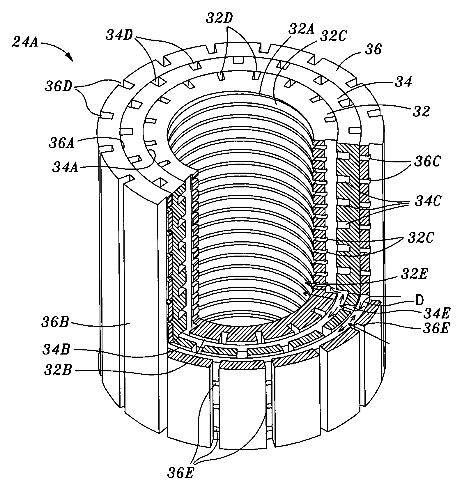
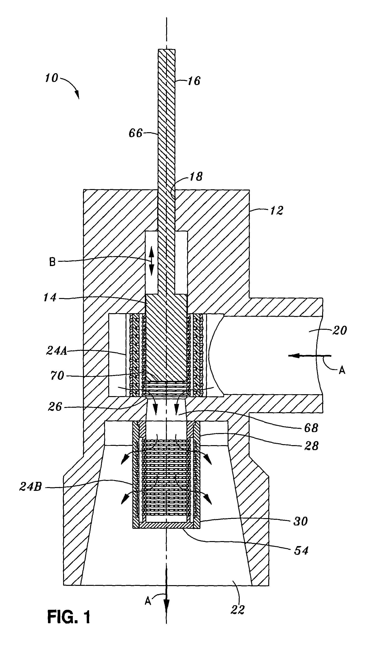
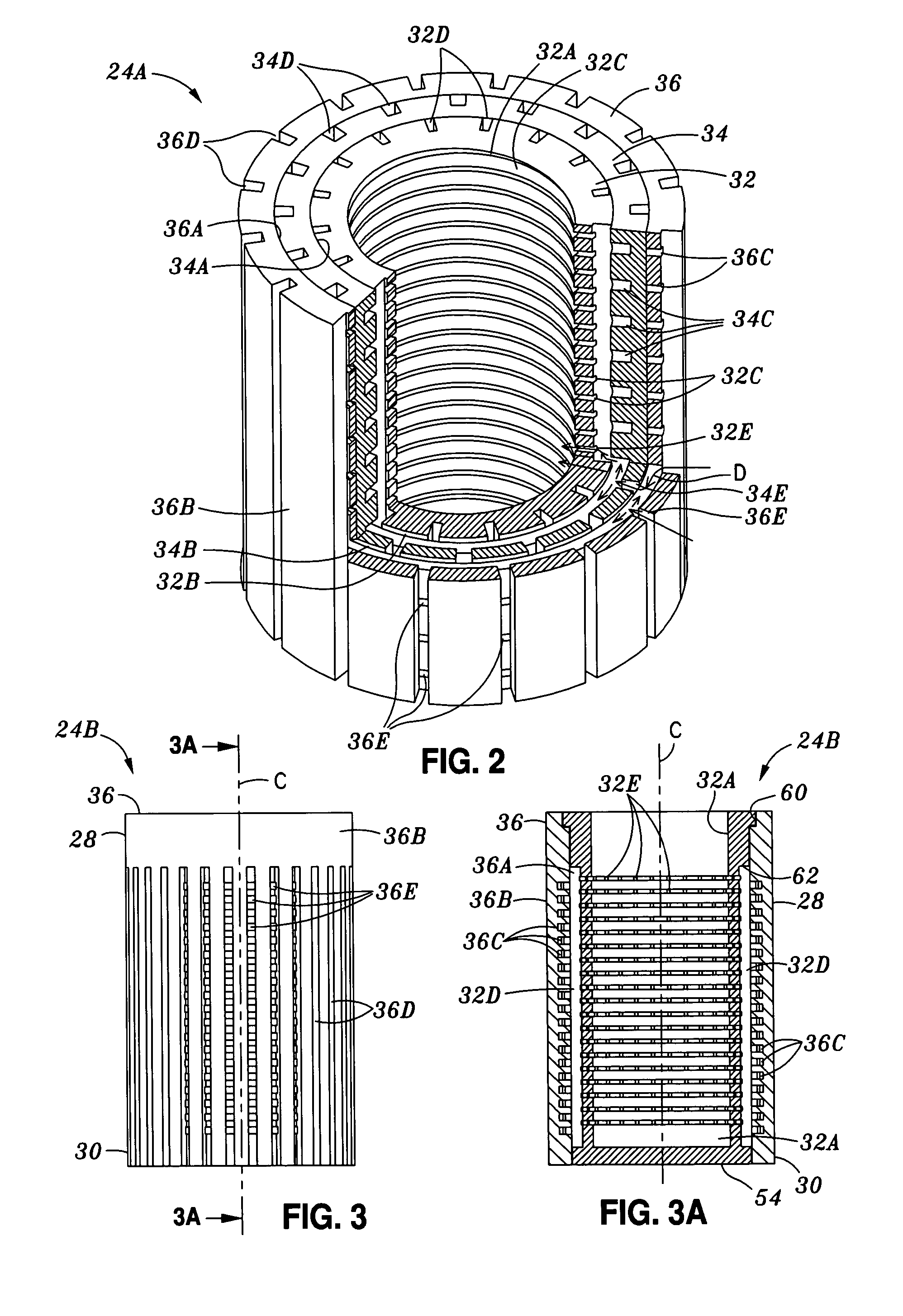
[0037]Referring now to the drawings wherein the showings are for purposes of illustrating the present invention and not for purposes of limiting the same, FIG. 1 illustrates a fluid control valve 10 comprised of a valve housing 12 having a fluid inlet chamber 20 and a fluid outlet chamber 22. The fluid inlet chamber 20 is in fluid communication with the fluid outlet chamber 22 via a flow opening 68 interposed therebetween. A first embodiment of a throttle device 24A of the present invention is shown in FIG. 1 disposed within the fluid inlet chamber 20 with a piston body 14 being slidably disposed within the throttle device 24A. A second embodiment of the throttle device 24B of the present invention is shown in FIG. 1 disposed within the fluid outlet chamber 22. A third embodiment of the throttle device 24C of the present invention is shown in FIG. 4 and 4A.

[0038]It should be noted that the first, second and third embodiments of the throttle devices 24A, 24B, 24C of the present inven...


PUM


Abstract

A throttle device comprises a tubular outer sleeve having a plurality of outer sleeve circumferential grooves formed on an outer sleeve inner surface and intersecting a plurality of outer sleeve axial grooves formed on an outer sleeve outer surface to form outer sleeve orifices. Also included is a tubular inner sleeve concentrically disposed within the outer sleeve and having a plurality of inner sleeve circumferential grooves formed on an inner sleeve inner surface. A plurality of inner sleeve axial grooves are formed on the inner sleeve outer surface and intersect the inner sleeve circumferential grooves to form inner sleeve orifices. The offset inner and outer sleeve orifices define tortuous flow paths wherein fluid flows into the outer sleeve axial grooves, through the outer sleeve orifices, through the outer sleeve circumferential grooves, through the inner sleeve axial grooves, through the inner sleeve orifices before exiting the inner sleeve circumferential grooves.

Description

CROSS-REFERENCE TO RELATED APPLICATIONS[0001](Not Applicable)STATEMENT RE: FEDERALLY SPONSORED RESEARCH / DEVELOPMENT[0002](Not Applicable)BACKGROUND OF THE INVENTION[0003]The present invention pertains generally to fluid control devices and, more particularly, to a throttle device for controlling and throttling high fluid pressures in equipment utilized in the oil, gas, and chemical industries as well as in power plants.[0004]The prior art includes many fluid control devices that are configured to control the velocity of the flowing fluid. These prior art devices are typically comprised of a hollow cylinder with an arrangement of orifices through which high-pressure fluid flows. The orifices may be formed by drilling or machining of the hollow cylinder. The passage of the high-pressure fluid through these orifices results in a pressure gradient across the inside and outside walls of the cylinder. Fluid control devices are a critical component in blow-off valves where they operate as ...

Claims


Application Information

Patent Timeline
Patent Type & Authority Patents(United States)
IPC IPC(8): F16K31/04F16K47/08F16L55/027
CPCF16L55/02763F16K47/08Y10T137/86791Y10T137/86759Y10T137/87917
Inventor BETH, HARALD
Owner CONTROL COMPONENTS INC
Why Eureka
Try Eureka