Drive assembly and motor vehicle equipped with drive assembly

a technology for motor vehicles and drive assemblies, which is applied in the direction of machines/engines, transportation and packaging, and warehousing. it can solve the problems of insufficient supply of oil, complicated drive assembly structure, and limited size and shape of troughs, so as to reduce the potential vibration of the drive assembly and save cost and space. the effect of requiring

Active Publication Date: 2012-09-18
TOYOTA JIDOSHA KK
View PDF15 Cites 12 Cited by
  • Summary
  • Abstract
  • Description
  • Claims
  • Application Information

AI Technical Summary

Benefits of technology

[0003]The drive assembly is typically provided in a limited space of a motor vehicle. This restricts the size and the shape of the catch tank and requires a long oil path for the oil feed to a distant site from the catch tank. Such restriction may give a complicated structure of the drive assembly and may cause insufficient supply of the oil to the distant site from the catch tank. The prior art drive assembly uses the driven gear of the differential arrangement to scoop up the oil into the catch tank. A relatively low vehicle speed naturally leads to a relatively low rotation speed of the differential arrangement and may cause inadequate scoop-up of the oil into the catch tank. Storage of a small quantity of oil in the catch tank under such conditions gives only the low cooling performance and the low lubricating performance and does not sufficiently lower the oil level of the oil pool. This does not sufficiently decrease the stirring resistance of the differential arrangement and undesirably increases the total energy loss of the drive assembly. A large-size differential arrangement eliminates such problems but undesirably occupies the limited space of the motor vehicle.

Problems solved by technology

This restricts the size and the shape of the catch tank and requires a long oil path for the oil feed to a distant site from the catch tank.
Such restriction may give a complicated structure of the drive assembly and may cause insufficient supply of the oil to the distant site from the catch tank.
A relatively low vehicle speed naturally leads to a relatively low rotation speed of the differential arrangement and may cause inadequate scoop-up of the oil into the catch tank.
Storage of a small quantity of oil in the catch tank under such conditions gives only the low cooling performance and the low lubricating performance and does not sufficiently lower the oil level of the oil pool.
This does not sufficiently decrease the stirring resistance of the differential arrangement and undesirably increases the total energy loss of the drive assembly.
A large-size differential arrangement eliminates such problems but undesirably occupies the limited space of the motor vehicle.

Method used


Image

  • Drive assembly and motor vehicle equipped with drive assembly
  • Drive assembly and motor vehicle equipped with drive assembly
  • Drive assembly and motor vehicle equipped with drive assembly

Examples


first embodiment

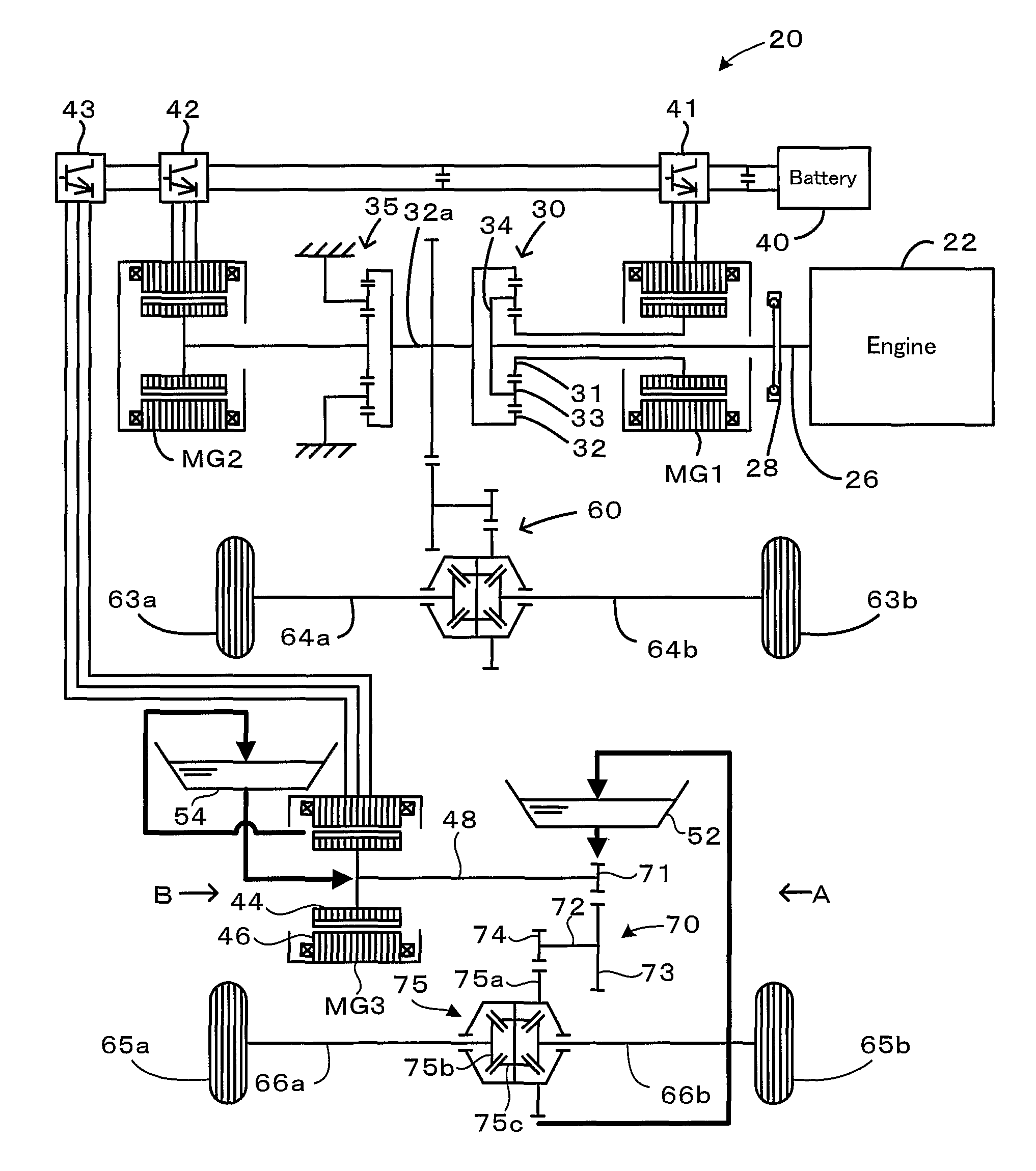
[0028]FIG. 1 schematically illustrates the configuration of a hybrid vehicle 20 equipped with a drive assembly in a first embodiment of the invention. As illustrated, the hybrid vehicle 20 is a four wheel-drive automobile having a front wheel drive system for driving front wheels 63a and 63b and a rear wheel drive system for driving rear wheels 65a and 65b, which is constructed as the drive assembly of this embodiment.

[0029]The front wheel drive system includes an engine 22, a planetary gear 30 having a carrier 34 that supports multiple pinion gears 33 and is connected to a crankshaft 26 of the engine 22 via a damper 28, a motor MG1 that is linked to a sun gear 31 of the planetary gear 30, a motor MG2 that is linked to a ring gear 32 of the planetary gear 30 via a ring gear shaft 32a and a reduction gear 35, and a gear train 60 that is connected with the ring gear shaft 32a and includes a differential gear linked to front shafts 64a and 64b of the front wheels 63a and 63b. The power...

second embodiment

[0043]A drive assembly of another configuration is described below as a second embodiment of the invention. The drive assembly of the second embodiment is also applicable as the rear wheel drive system of the hybrid vehicle 20 of the first embodiment. The like elements in the drive assembly of the second embodiment to those in the drive assembly of the first embodiment are expressed by the like numerals and symbols and are not described in detail.

[0044]FIG. 10 is a partially sectional view schematically illustrating the structure of primary part of a rear wheel drive system 100, which is mounted on the hybrid vehicle 20 as the drive assembly of the second embodiment. The rear wheel drive system 100 of the second embodiment shown in FIG. 10 has a transversely-arranged motor MG3 and a gear train 70 including a differential gear 75 that is connected to a motor shaft 48 of the motor MG3 and is linked to rear shafts 66a and 66b of rear wheels 65a and 65b. The power of the motor MG3 goes ...


PUM


Abstract

In a drive assembly of the invention, a first catch tank is provided above a casing that keeps lubricating oil accumulated in a bottom thereof for immersion of part of a rotor of a motor MG3 and of part of a differential ring gear of a differential gear. The first catch tank temporarily keeps the lubricating oil scooped up from the bottom of the casing by the rotation of the differential ring gear. The lubricating oil kept in the first catch tank is flowed down by the force of gravity and is fed to peripheral bearings. A second catch tank is arranged to temporarily keep the lubricating oil scooped up from the bottom of the casing by the rotation of the rotor of the motor MG3. The lubricating oil kept in the second catch tank is flowed down by the force of gravity and is fed to peripheral bearings. This arrangement desirably shortens oil paths connecting the respective catch tanks to the peripheral bearings and ensures smooth supply of the lubricating oil to all the peripheral bearings and other oil-requiring sites.

Description

TECHNICAL FIELD[0001]The present invention relates to a drive assembly that is mounted on a motor vehicle driven with power output to an axle and works to actuate the axle, as well as to a motor vehicle equipped with such a drive assembly.BACKGROUND ART[0002]In one proposed structure of a drive assembly, a driven gear of a differential arrangement works to scoop up the oil accumulated in an oil pool into an upper catch tank (see, for example, Japanese Patent Laid-Open Gazette No. 2004-180477). The prior art drive assembly feeds the oil kept in the catch tank to a motor through oil paths formed in a main shaft and a motor shaft, while feeding the oil from a motor chamber to respective parts of a reduction gear unit through an oil path formed in a counter shaft. These oil feeds aim at cooling the motor down and at lubricating the respective parts of the reduction gear unit. Storage of the oil in the upper catch tank intends to lower the oil level of the oil pool and thereby decrease t...

Claims


Application Information

Patent Timeline
Patent Type & Authority Patents(United States)
IPC IPC(8): F01M1/00B60K6/26B60K6/36B60K6/445B60K6/52B60L15/00F16H57/04
CPCB60K6/52F16H57/0447F16H3/727F16H57/0409F16H57/0423F16H57/0427F16H57/045F16H57/0457F16H57/0476Y02T10/6265Y02T10/62B60K6/22B60K6/36F16H57/04
Inventor IDESHIO, YUKIHIKONAGANO, SHUJIMORISAWA, KUNIOMAKI, HIROKIOKUDA, KOICHI
Owner TOYOTA JIDOSHA KK
Why Eureka
Try Eureka