Method and device for the continuous melting or refining of melts

a technology of melts and refining methods, applied in the direction of furnace components, lighting and heating apparatus, furnace types, etc., can solve the problems of high-purity glasses glass melts, premature end of production, wear of equipment, etc., and achieve the effects of low energy loss, lack of leakage protection, and lack of flashover resistan

Inactive Publication Date: 2011-10-06
SCHOTT AG
View PDF8 Cites 11 Cited by
  • Summary
  • Abstract
  • Description
  • Claims
  • Application Information

AI Technical Summary

Benefits of technology

[0021]The invention is aimed at avoiding the above-discussed drawbacks, such as lacking flashover resistance, high energy losses, and lacking leakage protection, while retaining the positive effects, such as high purity of the glass product and long service lives of the crucible.

Problems solved by technology

However, these have known drawbacks, such as, for example, a yellowing due to ionic platinum entrained into the glass melts and / or scattering effects on entrained platinum particles as well as streaks and other inhomogeneities due to dissolution of the silica glass crucible material in the glass melt.
In addition, glass melts for high-purity glasses and glass ceramics are often quite aggressive toward the crucible materials used in each case.
As a result, wear of the equipment and a premature end of the production occurs.
However, the melting method has the drawbacks presented below.
The necessary high operating voltages of greater than 1000 V result repeatedly in flashovers, mostly between the coil and the crucible, especially in dusty surroundings.
This can result in long-lasting interruptions in operation and thus lead to high production costs.
The high voltages pose a potential source of danger for the persons operating the unit.
The construction of the crucible is time-consuming and cost-intensive due to the complex design.
This results in additional costs.
As a result, idle powers of 10 to 20% of the total power are created, in particular due to the voltage drop at the crucible.
However, the melting devices described in the documents presented above cannot be used for the production of glass or glass ceramics, because these two classes of substance tend to form only relatively thin sinter crusts.
Flashovers can result between the coil and the glass volume.
Furthermore, there exists the drawback that the thin skull layer leads to the dissipation of a large amount of energy from the melt volume to the cooling water.
This often results in the crust not being rigid, but rather remaining soft and deformable.
This crust in glasses is often, therefore, not all too durable mechanically.
In the case of large melting units exhibiting a high hydrostatic pressure, by contrast, this can result in a breakthrough with subsequent leakage of the charging material.
Moreover, energy is absorbed in the coil, which functions as inductor, and in the metallic bottom and is no longer available for the melting process.
Opposed to the use of ceramics in the melting unit, however, is the high corrosiveness toward ceramic materials that many glass and glass ceramic melts display.
If ceramics made of refractory components are used for the melting unit, therefore, there is no adequate leakage protection.
In addition, the dissolution products of the ceramic linings result in streaks, bubbles, discolorations, and other flaws in the glass, which can substantially impair the quality of the product.
The crucibles described therein, however, exhibit the drawback that their service lives are relatively short.
Accordingly posed is the problem of providing a method and a device for the direct heating of glass melts by means of electromagnetic fields, in which the melting operation or the refining operation takes place continuously.

Method used


Image

  • Method and device for the continuous melting or refining of melts
  • Method and device for the continuous melting or refining of melts
  • Method and device for the continuous melting or refining of melts

Examples


Embodiment Construction

[0089]Devices for the discontinuous production of glass products from a glass melt, which are also referred to as skull crucibles, may be taken, for example, from the German Patent Application DE 10 2006 004 637.4 with the title “Inductively Heatable Skull Crucible,” the contents of which are assumed to be known in the following description. Consequently, because it is known to the skilled practitioner in this field and also for reasons of clarity, an unnecessary description of additional device and method parts that are already known from this publication will be dispensed with below.

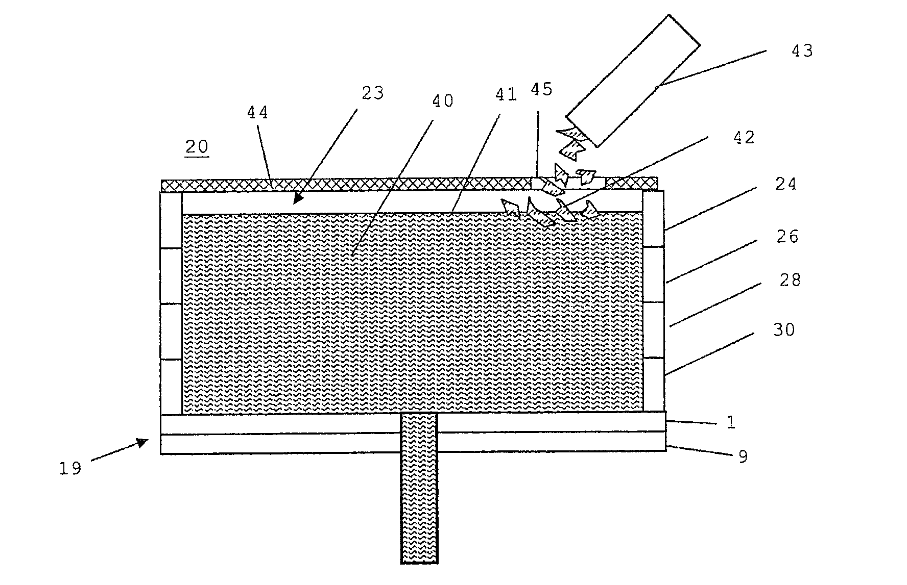
[0090]The inductor crucible 20 (FIG. 5) is conventionally fabricated from copper or from aluminum.

[0091]However, it can also consist of other materials, such as, for example, a Ni-based alloy, and may optionally be coated with Teflon or another material.

[0092]The inductor crucible is furnished with a protective layer 21, as described in more detail below, on the side (interior side) facing the charging...


PUM

PropertyMeasurementUnit
temperatureaaaaaaaaaa
electrical conductivityaaaaaaaaaa
frequencyaaaaaaaaaa

Abstract

A method for the continuous production of products from a melt is provided. The method includes heating the melt to a predetermined temperature in a skull crucible, the bottom of which is formed from electrically non-conductive, but thermally conductive material.

Description

CROSS REFERENCE TO RELATED APPLICATIONS[0001]This application claims benefit under 35 U.S.C. §119(a) of German Patent Application No. 10 2009 033 501.3, filed Jul. 15, 2009, the entire contents of which are incorporated herein by reference.BACKGROUND OF THE INVENTION[0002]1. Field of the Invention[0003]The invention relates to a method and a device for the continuous production, in particular, of glass and glass ceramic products from a glass melt.[0004]2. Description of Related Art[0005]Glass products, such as, in particular, high-purity glasses and glass ceramics, are generally produced in melt vessels from noble metals, such as platinum or platinum alloys, as well as from silica glass. However, these have known drawbacks, such as, for example, a yellowing due to ionic platinum entrained into the glass melts and / or scattering effects on entrained platinum particles as well as streaks and other inhomogeneities due to dissolution of the silica glass crucible material in the glass mel...

Claims


Application Information

Patent Timeline
Patent Type & Authority Applications(United States)
IPC IPC(8): F27D3/00
CPCC03B5/021C03B5/42F27D1/0043C03B2211/70F27B14/063C03B5/43
Inventor KOLBERG, UWENUETTGENS, SYBILLGROSS, ANDREAS
Owner SCHOTT AG
Why Eureka
Try Eureka