Manufacturing method for fuel cell

a manufacturing method and fuel cell technology, applied in the manufacture of final products, fuel cell details, electrochemical generators, etc., can solve the problems of increasing energy loss resulting from heating, not being able to suppress an increase in manufacturing cost, and not being able to heat only the thermoplastic adhesive, etc., to suppress an extension of manufacturing time and increase manufacturing cost

Active Publication Date: 2018-06-07
TOYOTA JIDOSHA KK
View PDF11 Cites 10 Cited by
  • Summary
  • Abstract
  • Description
  • Claims
  • Application Information

AI Technical Summary

Benefits of technology

[0015]It is possible to provide a manufacturing method for a fuel cell, which sup

Problems solved by technology

In addition, it is not possible to heat only the thermoplastic adhesive, and the portions around the separators and the support frame need to be heated to such an extent that the thermoplastic adhesive melts in ant

Method used


Image

  • Manufacturing method for fuel cell
  • Manufacturing method for fuel cell
  • Manufacturing method for fuel cell

Examples


Embodiment Construction

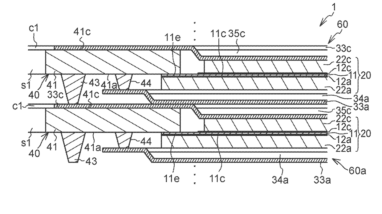
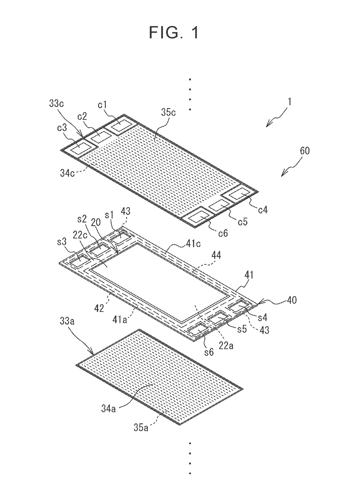
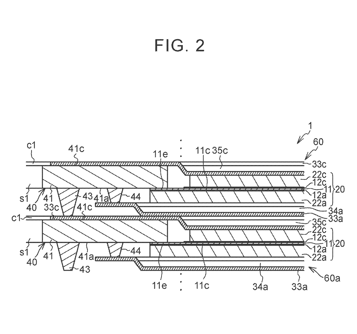
[0033]FIG. 1 is an exploded perspective view of each single cell 60 of a fuel cell 1. The fuel cell 1 is formed of a plurality of the single cells 60 stacked on top of each other. The fuel cell 1 is a polymer electrolyte fuel cell that generates electric power upon reception of a supply of fuel gas (for example, hydrogen) and oxidant gas (for example, oxygen) as reactant gases. Each single cell 60 includes a membrane electrode gas diffusion layer assembly 20 (hereinafter, referred to as MEGA), a support frame 40, a cathode separator 33c (hereinafter, referred to as first separator) and an anode separator 33a (hereinafter, referred to as second separator). The support frame 40 supports the MEGA 20. The first separator 33c and the second separator 33a sandwich the MEGA 20. The MEGA 20 includes an anode gas diffusion layer 22a and a cathode gas diffusion layer 22c (hereinafter, referred to as diffusion layers). The support frame 40 has a substantially frame shape. The inner peripheral ...


PUM


Abstract

A manufacturing method for a fuel cell includes: preparing a membrane electrode gas diffusion layer assembly; preparing a support frame having an electrical insulating property and an ultraviolet permeability; preparing a separator; bonding the membrane electrode gas diffusion layer assembly and the support frame to each other via a first ultraviolet curable adhesive; and, after the membrane electrode gas diffusion layer assembly and the support frame are bonded to each other, bonding the support frame and the separator to each other via a second ultraviolet curable adhesive.

Description

INCORPORATION BY REFERENCE[0001]The disclosure of Japanese Patent Application No. 2016-234472 filed on Dec. 1, 2016 including the specification, drawings and abstract is incorporated herein by reference in its entirety.BACKGROUND1. Technical Field[0002]The disclosure relates to a manufacturing method for a fuel cell.2. Description of Related Art[0003]There is known a single cell of a fuel cell. The single cell includes a membrane electrode gas diffusion layer assembly, a support frame and a pair of separators.[0004]The support frame supports the membrane electrode gas diffusion layer assembly. The pair of separators sandwich the membrane electrode gas diffusion layer assembly and the support frame. For example, in Japanese Patent Application Publication No. 2016-162650 (JP 2016-162650 A), a peripheral region of a membrane electrode gas diffusion layer assembly, at which an electrolyte membrane is exposed, is bonded to a support frame by an ultraviolet curable adhesive, and separator...

Claims


Application Information

Patent Timeline
IPC IPC(8): H01M8/1004H01M8/0273H01M8/0202
CPCH01M8/1004H01M8/0273H01M8/0202H01M8/0247H01M8/2418Y02P70/50Y02E60/50
Inventor OKABE, HIROKI
Owner TOYOTA JIDOSHA KK
Why Eureka
Try Eureka