

Receptacle, printed wiring board, and electronic device
a technology for electronic devices and wiring boards, applied in the direction of printed circuit aspects, coupling device details, coupling device connections, etc., can solve the problem of increasing and achieve the effect of suppressing the increase in the cost of manufacturing printed wiring boards
- Summary
- Abstract
- Description
- Claims
- Application Information
AI Technical Summary
Benefits of technology
Problems solved by technology
Method used
Image

Examples
first embodiment
[0026](Interface Configuration)
[0027]The configuration of an interface according to a first embodiment will be described with reference to the drawings. The present embodiment will describe an interface 10, based on the HDMI (High-Definition Multimedia Interface)® standard, as an example of an interface between electronic devices. Note that “electronic device” refers to, for example, an Audio-Visual device, a mobile terminal, a personal computer, or the like.
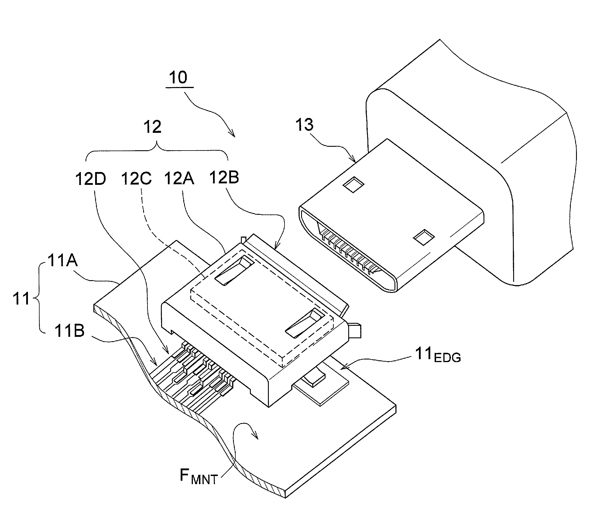
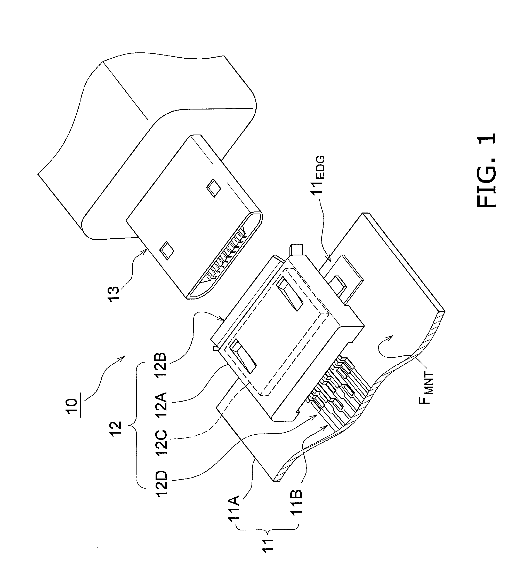
[0028]FIG. 1 is a perspective view illustrating the configuration of the interface 10 according to the first embodiment. As shown in FIG. 1, the interface 10 is configured of a printed wiring board 11, a receptacle 12, and a plug 13.
[0029]The printed wiring board 11 is installed within a first electronic device (not shown). The printed wiring board 11 includes a main substrate 11A and a wire group 11B. The main substrate 11A has a mounting face FMNT. The configuration of the printed wiring board 11 will be described later.
[0030]...
second embodiment
[0096]Next, the configuration of a printed wiring board 11 and a receptacle 12 according to a second embodiment will be described with reference to the drawings. Hereinafter, the differences from the first embodiment will mainly be described. The difference from the first embodiment is that the printed wiring board 11 includes multiple rearwardmost-row lands Ln instead of the multiple forwardmost-row lands Lm.
[0097](Receptacle Configuration)
[0098]First, the configuration of the receptacle according to the second embodiment will be described with reference to the drawings. FIG. 7 is a perspective view illustrating the internal configuration of the receptacle 12 according to the second embodiment. The housing 12A has been omitted from FIG. 7.
[0099]In the present embodiment, the ground terminal TG1 and the ground terminal TGC are formed so as to be shorter in the extension direction than the other top terminals TTOP.
[0100]Meanwhile, the vertical positions of the ground terminal TG1 and...
third embodiment
[0123]Next, the configuration of a receptacle 12 according to a third embodiment will be described with reference to the drawings. Hereinafter, the differences from the second embodiment will mainly be described. The difference from the second embodiment is that the pair of signal terminals TS1− and TS1+ are twisted by approximately 90 degrees.
[0124]Hereinafter, the pair of signal terminals TS1− and TS1+ will be described as an example. However, it should be noted that this configuration is not limited to the pair of signal terminals TS1− and TS1+, and can be applied in the pair of signal terminals TSC− and TSC+.
[0125](Terminal Configuration)
[0126]The configuration of the terminals according to the third embodiment will be described with reference to the drawings. FIG. 10 is an enlarged perspective view illustrating a pair of signal terminals TSC− and TSC+ according to the third embodiment.
[0127]Each of the terminals in the pair of signal terminals TSC− and TSC+ has a link portion 4...
PUM
 Abstract
Description
Claims
Application Information