Methods and apparatus for battery charging management

a technology of battery array and charging management, which is applied in the direction of battery overheating protection, safety/protection circuit, transportation and packaging, etc., can solve the problems of limited electric voltage and current delivered by the rechargeable battery array, and long charging time of the cells in the battery array. , to achieve the effect of reducing heat generation, effective dissipation of heat, and difficult charging up the cell

Inactive Publication Date: 2009-10-01
1POWER SOLUTIONS
View PDF3 Cites 43 Cited by
  • Summary
  • Abstract
  • Description
  • Claims
  • Application Information

AI Technical Summary

Benefits of technology

[0010]The large amount of excessive heat generated may lead to high temperature conditions in the battery array if the heat is not efficiently dissipated to the environment. Such high temperature conditions have detrimental effects such as burn up of electronics circuits. In some battery, the electrolyte and separator may break down and result in gassing at the anode to release oxygen. The oxygen makes it more difficult to charge up the cell, and may ignite to cause explosion at sufficiently high temperature under the high pressure inside the cell. Such an effect is accelerated at higher operational temperatures. Such battery failure must be avoided because the effect is hazardous especially to running vehicles. Known methods to deal with the heat problem include utilization of complicated ventilation system, and large heat sinks. Instead of reducing heat generation by the heat sources, most of the existing solutions try to dissipate heat effectively by adopting expensive thermodynamic system for heat dissipation which however disadvantageously increase the manufacturing cost as well as the size of the battery system.
[0011]In addition, the electrical energy for charging battery is also wasted as heat energy resulting inefficient charging. This substantially increases the electric bill of the user especially for applications such as the BEV, in which the charging process is a day to day operation.
[0012]A need therefore exists for methods and apparatus to manage the charging of a battery array such that heat generation during charge balancing is substantially reduced.
[0013]It is the objective of the presently claimed invention to minimize heat generation during charge balancing and reduce the time that charge balancers are turned on, hence reduce the current through the charge balancers.

Problems solved by technology

The electrical voltage and current delivered by a rechargeable battery is limited by the battery chemistry.
Series cell configuration, however, suffers from a problem that, if one cell charges up faster than its neighbor, the full cell will limit the charging current flowing into the non-full cells.
As a result, some of the cells in the battery take a long time to charge up and the charging process is inefficient.
As a result, the overall energy storing capacity of the battery cannot be fully utilized.
The problem of unbalanced charging also gets more serious, and undesirably wastes a significant portion of the battery capacity.
Apart from unbalanced charging, intrinsic faults in cells may also limit the charging current to neighbor cells.
Even if the user can tolerate a long charging time and the limited charging current may at long last charge up other cells, another problem is caused by the continuous application of charging current to those fully charged cells.
As a result, the cell life may be substantially shortened.
Such steps result in extra manufacturing costs and time.
Furthermore, the step of cell matching only improves unbalanced charging by trying to minimize the difference of charging capacity between cells, however difference in charging capacity still exists and the problem is not ultimately solved.
In addition, significant capacity mismatch still happens in spite of initial cell matching when the battery cells start to degrade after prolonged use.

Method used


Image

  • Methods and apparatus for battery charging management
  • Methods and apparatus for battery charging management
  • Methods and apparatus for battery charging management

Examples


Embodiment Construction

[0036]The present invention is described in detail herein in accordance with certain preferred embodiments thereof. To describe fully and clearly the details of the invention, certain descriptive names were given to the various components such as controller, digital signal processor, and frequency multiplier. It should be understood by those skilled in the art that these descriptive terms were given as a way of easily identifying the components in the description, and do not necessary limit the invention to the particular description.

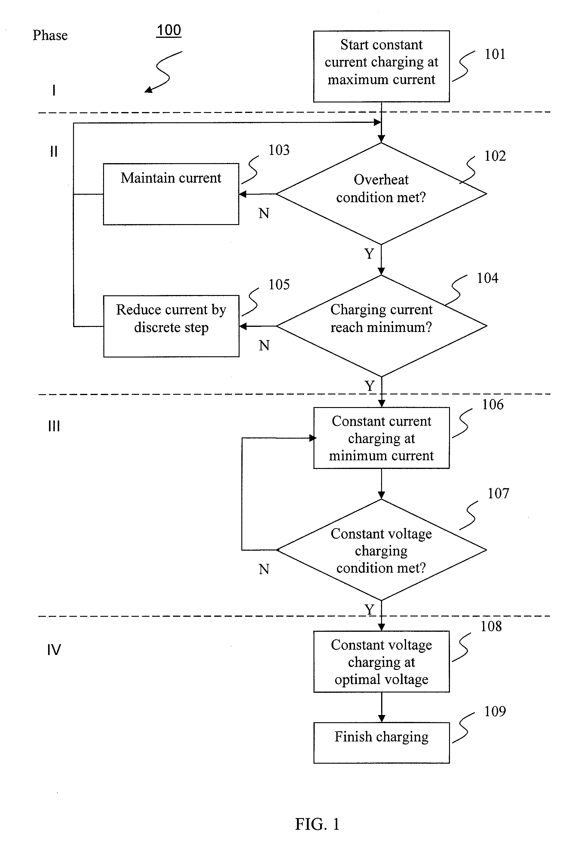
[0037]FIG. 1 is a flow diagram 100 illustrating the battery management system for charging a battery array according to an embodiment of the presently claimed invention. Processing commences in maximum current charging step 101 where an array of battery cells is charged by a constant current. The charging current at this stage is preferred to be as large as possible in order to speed up the charging process but in the meantime not damaging the battery c...


PUM


Abstract

A method for managing the charging of a battery array 100, including the steps of: charging the battery array with a constant current at maximum rating 101; monitoring the status of a plurality of partitions among the battery array for overheating conditions 102; reducing the charging current to turn off charge balancing when overheat conditions are detected in any of the partitions 105; maintaining the charging current when overheat conditions are eliminated in all of the partitions 103; and repeating the steps of reducing and maintaining charging current until the charging current reaches the optimum rating where heat generated thereby can be tolerated.

Description

TECHNICAL FIELD[0001]The present invention relates to methods and apparatus for charging a rechargeable battery array and further relates to methods and apparatus of reducing heat generated by charge balancer when charging a battery array.SUMMARY OF THE INVENTION[0002]The rechargeable battery has been widely used as power source for low power consumption electronic devices such as digital cameras, laptop computers, and mobile phones. The electrical voltage and current delivered by a rechargeable battery is limited by the battery chemistry. Recent development in battery technology has overcome challenges such as high energy density and long cycle time, making heavy duty applications possible. Rechargeable batteries are now available for Battery Electric Vehicles (BEV), hybrid vehicles, and load leveling machines.[0003]Rechargeable batteries can increase the output power by configuring voltaic cells in parallel, series, or in both to form an array structure. A parallel configuration o...

Claims


Application Information

Patent Timeline
Patent Type & Authority Applications(United States)
IPC IPC(8): H02J7/04H02J7/00
CPCH02J7/0016Y02T10/7055H02J7/0026Y02T10/70H02J7/00309H02J7/007194
Inventor CHOI, KAI-WAI ALEXANDERCHAN, SHEUNG WA
Owner 1POWER SOLUTIONS
Why Eureka
Try Eureka